64 KiB
Every beginning is easy
The tutorial introduces you to the simple operation of MaxonCINEMA 4D using examples. The tutorial does not require any previous knowledge of using MaxonCINEMA 4D. You should only have the general basic knowledge of how to use the Amiga and the Workbench. If you don't feel challenged, you can skip the tutorial and study the reference.
1. The user interface
When programming MaxonCINEMA 4D, despite the wide range of functions, great importance was attached to user-friendliness. The user interface of MaxonCINEMA 4D adheres strictly to the guidelines for programs specified by Commodore. All functions and commands are in German and care has been taken to ensure that the input options are consistent. This means that certain program elements that appear frequently always have the same meaning and function. In addition, there is no function without feedback. MaxonCINEMA 4D will notify you of incorrect entries. If MaxonCINEMA 4D is busy with a longer calculation, the wait pointer always appears. Another unique feature of MaxonCINEMA 4D is the ability to stop drawing a document at any time. This eliminates the hassle of waiting for the screen to refresh. All this should guarantee you a quick and uncomplicated training.
If you have started MaxonCINEMA 4D and go through the menu functions with the right mouse button pressed, you will find that three different types of menu entries can be identified. On the one hand, there are menu entries that only have one word, such as "delete". This means that the corresponding function is executed immediately after you have selected it.
On the other hand, there are menu items with three dots after the name, such as "Open..." or "Add...". The subscripts mean that the function is not executed immediately after it is called. First a window appears in which you have to enter additional information about the function before it can be executed by clicking on the "OK" field.
In addition, there are functions that you can either run immediately with preset values or where you have the option of changing the parameters. In order to avoid menu items appearing twice - once with subscripts and once without - additional trailing dots (*) have been introduced in MaxonCINEMA 4D. If you call a function with such a trailing dot, such as "ring *", the function is executed immediately, in this case a ring appears, for example. If you try the same thing again while holding down the Shift key, a window will appear in which you can specify the function.
A great advantage of MaxonCINEMA 4D is that values once set in a window can be remembered.
There are keyboard shortcuts for almost every function. There is a combination of letters after each menu item. For example, pressing the combination + means that the "Open" function is invoked. This saves you having to switch from the keyboard to the mouse, making it possible to work smoothly.
The same applies to the fields of input windows, almost all of which can be activated by pressing a specific letter. You can tell which letter this is in each individual case from the field name. The relevant letter is underlined there.
The letters "O" and "A" are always reserved for the "OK" and "Cancel" fields in windows. You can also cancel at any time with the key.
If you confirm with "OK", all values are immediately checked for validity. For example, if you have entered an angle of 92.3° that is too large, although only 90° is permitted, MaxonCINEMA 4D will draw your attention to this and at the same time tell you in which range the correct value must lie.
To enter data quickly in windows with many number fields, you only need to press the Tab key and the number fields will be activated one after the other. If you also hold down the Shift key, you can jump backwards. You can also do the same with the arrow keys (up and down).
2. All a matter of view
There are various methods for entering three-dimensional objects on the only two-dimensional screen.
One method is to bring three-dimensional space onto the screen using various parallel images. This type of mapping includes plan (XY view), elevation (XZ view), and side elevation (ZY view).
In these views, the coordinate axes are always displayed with their designation, so that you can orientate yourself. In MaxonCINEMA 4D, the convention is that the "X" axis is to the right, the "Y" axis is up, and the "Z" axis is backwards away from you.
You can change the view at any time while working or move the visible workspace with the mouse.
-
Start MaxonCINEMA 4D.
The main toolbar appears on the interface and a document window in which a perspective grid is drawn.
-
In the "Objects/Basic Objects" menu, select the "Ring" menu item.
You see the ring in perspective in the "3D" view.
-
 Click on the "XZ" icon on the main bar.
The ring now appears in plan, that is, it is shown from above.
-
Left-click anywhere in the document window, hold the left mouse button down, and move the mouse and observe the desktop.
As long as you keep the button pressed, the working surface with the ring, the coordinate axes and the grid moves according to your mouse movement. For reasons of speed, the ring is not drawn during the movement. Instead, a bounding rectangle is displayed. As soon as you release the button, the desktop stops.


The mouse input affected the view in this way because the "Edit View" icon was set in combination with the "Move" icon.


With the top 6 symbols of the main bar you always specify which screen elements you want to edit - in this case the view. The other 5 symbols are used to change the points of an object, the object itself, its axes, its texture or its texture axes.
Now look at the next 4 symbols. Use this to select the action you want to perform. Because the pan arrow is currently activated, you can pan the view with the mouse. On the other hand, if you want to enlarge the section, then the "Scale" symbol to the right is responsible for this.
-
 Click on the 'Scale' icon, place the mouse anywhere in the document window as before and move the mouse while holding down the left mouse button.
You will see how the visible section increases or decreases depending on whether you move the mouse to the left or to the right.
Sometimes it is very difficult to visualize an object based on the floor plan, side elevation and elevation. In this case, working in the three-dimensional view (3D view) is a good idea. Here the objects are not flattened, instead you view the scene from the point of view of an imaginary camera and see the scene in perspective. Objects further away from your point of view appear smaller than those that are close. In order for the camera to know in which direction to look from its position, a viewing direction must always be specified in addition to the camera position. But no fear. You can use the 3D view just as easily as you could previously move the workspace with the mouse.
-
 Switch back to the "3D" view by clicking the "3D" icon.
You now see the view from the camera's point of view in front of you. A grid is drawn in the XZ plane in the document window. It is intended to serve as an orientation aid. You can also see the ring drawn in white and shown in perspective.
-
 Now click on the "Rotate" icon and move the mouse again while holding down the left button.
This time you can move the editor camera around the ring in real time. A right-left movement rotates the camera horizontally, an up-down movement across the ring.
-
Try the same with the "Move" icon and the "Scale" icon as well.
You can see how you can move the camera freely in space.
If you have activated the "Move" symbol, you can actually only change two coordinates at a time with the mouse, e.g. the X-axis (right-left) and the Y-axis (up-down). But if you use the right mouse button instead of the left one, you can also change the Z coordinate.
-
Try the right mouse button function.
You can also switch between the right and left mouse button during the moving process!
In addition to the individual two-dimensional projections (floor plan, elevation, side view) and the editor camera (3D view), you can display these four views simultaneously for the best possible overview.
-
 Click on the "4T" icon.
All four views appear simultaneously in the document window
-
Activate the "Move" icon and click with the mouse in the upper left quarter of the window with the "3D" view. As before, you can move the camera with the mouse while holding down the mouse button.
You'll see the camera view change, but the other three views remain unaffected.
-
Click in one of the other views and move the mouse while holding down the button.
You'll notice that the camera view doesn't change now, but the three two-dimensional views do.
Why are there single views at all?
The clearest way to work is in the 4T view. Nevertheless, it has certain disadvantages. Since each individual view only takes up a quarter of the screen area, details are no longer so easy to see. In addition, the screen structure takes more time, but this is only noticeable with larger objects.
You can now use your desktop quite well. But there are still a number of helpful functions that support you in your work.
First of all, there is the magnifying glass. You can use it to specifically enlarge a specific area of the work surface.
-
Go to 3D view.
-
 Click and hold the 'magnifying glass' icon. A drop-down menu with various options will appear. You can see that there is a drop-down menu under this symbol by the small black triangle in the lower right corner.
Select the magnifying glass option. The mouse pointer immediately changes to a crosshair. Press the left mouse button above the ring on the left and keep it pressed. Now move the mouse. MaxonCINEMA 4D draws a frame. This delimits the area which is to be shown enlarged afterwards. Drag the frame to about the middle of the ring and release the left mouse button.
MaxonCINEMA 4D immediately expands the work surface.
Now that you've looked at the ring magnified, it should be fully visible again.
-
Click the magnifying glass icon again, but this time select the Active Object option.
This prompts MaxonCINEMA 4D to select the magnification and section in such a way that the active object - in our case the ring - fills the format. If, on the other hand, you select the "Entire Scene" option, MaxonCINEMA 4D changes the values so that all objects in the document are displayed in full format.
A very useful function is the display of a grid of lines on the screen. You can use this grid as a guide and position objects more easily. Like many other important tools, the grid is housed in the so-called "Information" window. This has several switchable pages, e.g. for the position of an object or the position of the camera.
-
Open the information window by selecting the menu item "Window/Information". If the information window is open, this is indicated by a tick in front of this menu item.
In the lower right corner of the information window you will find the "About" field with which you can select the page that is currently displayed.
-
Select the "View" page.
The position and direction of the camera appears, as well as the settings for the individual grid types.
Here you can set whether you want to see a line grid at all (this is the visible grid on the screen) and what spacing the grid should have. The other grid types "move grid", "scale grid" and "rotate grid" (these are invisible grids) only come into their own when objects are moved, scaled or rotated.
The ticks in front of the respective grid types indicate whether they are active. The numeric values behind the names indicate the grid width.
In principle, you can not only view all displayed values and parameters, you can also change them. Simply click on the corresponding value and change it with the keyboard.
-
 Go to XY view.
 -
Click on the line grid value, change it to 50 and press Enter.
The surface now has a finer grid. Incidentally, the grid disappears from a certain reduction in the size of the workspace, since it would otherwise be too close together.
-
Now set the values 5 for the displacement grid and 100 for the line grid so that you can work through the following sections well.
3. Working with objects
It is often not easy, especially for beginners, to enter new objects. For this reason, MaxonCINEMA 4D has a number of basic objects built in, with which complex objects can be put together — similar to building blocks.
In the "Objects/Basic objects" menu you will find them sorted alphabetically, e.g. the objects "Triangle", "Square", "Cube", "Pyramid", "Tetrahedron" and "Plane".
You can create a basic object by selecting the corresponding menu item. The object then appears in the middle of the visible workspace with preset values for size and subdivisions. If you want to change these values, hold down the shift key when you call up the menu item.
But you can also use the object bar. This can be opened just like the "Information" window in the "Window" menu.
 To do this, select the "Object bar" menu item and click on the "Basic objects" symbol with the mouse.
A drop-down menu appears with the same options as in the "Objects > Primary Objects" menu.
| Brief description of the most important basic objects | |
|---|---|
| triangle | You can specify the height and width of the triangle. The triangle is right angled and always appears parallel to the XY plane of the world coordinate system. |
| level | The level is made up of many squares, which together form one large square. It always appears parallel to the XZ plane of the world coordinate system and is primarily intended for later changes using functions such as "Crinkle" or "Deform". You can enter the width, the length and the number of the respective subdivisions. |
| cone | You can create the cone with or without a floor, depending on whether you have the Floor check box turned on. Otherwise you can also specify the radius of the bottom surface, the height of the cone and the number of subdivisions. |
| bullet | The sphere has an important feature. You can create a real, mathematically perfect sphere as well as an object composed of triangles and squares. The difference can be seen above all in the subsequent image calculation. The perfect sphere always looks the best and is calculated very quickly, while the sphere made up of surfaces can be recognized by the angular outline. For this, only the flat sphere can be post-processed with functions such as "Crinkle" or "Deform". For such a sphere you can determine the number of subdivisions. Mathematically perfect spheres are represented on the workspace by their outline. |
| pyramid | You can enter the edge length of the base and the height of the pyramid. It is a four-sided pyramid. |
| ring | In addition to the subdivisions, you can also determine the radius of the ring and the radius of the tube. The ring is always composed of squares. |
| tetrahedron | This object is composed of four equilateral triangles. You can enter the edge length of the triangles and the height of the tetrahedron. |
| square | Here you can specify the height and width of the square. The square always appears parallel to the XY plane of the world coordinate system. |
| dice | The cube is made up of 6 squares. In the input field you can specify the edge length of the cube and determine whether the side faces should be separated into individual objects. |
| cylinder | In addition to the radius, you can determine the length of the cylinder. The cylinder surface is made up of squares, the number of which you determine with the value for subdivisions. If you also want the cinder not to be hollow, but to have a bottom and top surface, then switch on the "Cover surfaces" checkbox. |
For all objects that require an indication of the number of subdivisions, the more subdivisions they have, the finer and rounder they appear. However, the objects then also require more storage space and computing time.
-
Call up the various primitive objects.
Any reasonably realistic looking scene needs a background. This shouldn't just be a still image (which is also possible with MaxonCINEMA 4D), but should convey a convincing impression of depth depending on the location of the camera. In addition, there is the "floor" in MaxonCINEMA 4D, which is always located exactly in the XZ plane and has infinite expansion. However, the floor is not displayed in the editor, since the cracks always make it clear where the XZ plane is and additional grid lines would only complicate the display. The bottom is only displayed in the perspective views described later.
Similarly, "heaven" is an infinitely extended sphere arching over the ground. The sky is also only visible in one of the perspective views.
-
Select the "Ground" and "Sky" functions in the "Objects" menu one after the other. The two menu items are now marked by a tick in front of the name.
Ground and sky are somewhat special, as they can only exist once each and are also subject to certain restrictions. They cannot be moved or scaled because they have infinite dimensions.
With the text function of MaxonCINEMA 4D it is possible to do professional video titling. You enter any text that MaxonCINEMA 4D then converts into three-dimensional letters.
-
 Select the "Text" function from the "Objects/Special Objects" menu.
A window appears in which you can enter a text. In addition, you can determine which of the supplied 3D character sets should be used.
-
Enter the text "MaxonCINEMA 4D" in the text field and click "OK".
MaxonCINEMA 4D now loads the required letters from the hard disk and draws them on the desktop.
Now that you're able to create all sorts of objects, it's time to explore the features for saving your work.
-
Access the "Save As" function from the "Project" menu.
The file selection window familiar from the workbench appears. In it you can enter information about the name of your document and the file path.
-
Enter the name "Test" in the "File" text entry field and confirm with "OK".
Another window appears with many ticks, but you should not be interested in this. Just click OK again.
Your scene is now saved under the name "Test". Check this by closing the document window.
-
Click on the close icon of the document window.
-
Call the "Open" function from the "Project" menu.
The file selection window appears again.
-
Select the previously saved "Test" scene and click "OK".
A document window appears again with the scene as before saving.
-
Change the scene as you like, for example by adding a few more objects.
In order to save the change you have just made, you no longer need to use the cumbersome "Save as" function. Instead, simply select the "Save" function in the same menu. The scene is immediately saved under the previously used name without prompting. This is also always displayed in the title bar of the document. As long as you haven't entered a name, "Untitled" always appears.
You should make it a habit to save your scene every half hour or so when working with Maxon CINEMA 4D. A power outage doesn't happen often, but it's all the more annoying the more work you've put into the scene you're editing. It can also happen that you have deleted several objects and later realize that you still need them afterwards.
4. Three selection processes
As you may have noticed, only the newly added object is drawn in white. All other objects are drawn in light gray. In MaxonCINEMA 4D terminology, one also speaks of active (white) and inactive (light gray) objects. This distinction is important because MaxonCINEMA 4D always needs to know which object certain functions refer to. For example, almost all menu items from the "Tools" menu always refer to the active object.
There are several methods to activate an inactive object:
The easiest way is to click on the black dot that is drawn for each object. This marks the origin of the object coordinate system and is also used for selection. This object will be activated immediately.
-
Close the document and choose New from the Project menu. Switch to the XY view and use the text function to create the text "Activation".
-
Try activating the letters of the lettering by clicking on the black dots one after the other.
There is another method to select objects.
-
Activate the letter "g" by calling the "Select object" function from the "Edit" menu.
With this function you can activate an object based on its name. An alphabetical list of all objects in the scene appears. Among other things, you can see that each letter of the text you just created exists as an object titled "Activation." The type of object is always displayed to the left of the name. In addition to area objects, these can also be light sources or polygons.

As you can see there is also a small black arrow next to the dice symbols. This indicates that all letter objects themselves consist of other objects.
-
Double click on the letter "g".
This takes you - similar to the Amiga operating system - one hierarchical level (drawer) deeper and you can now see the sub-objects.
-
Click on the "Higher" button. You are back on the higher level. Click "Up" again. You will now see the overall object "Activation".
-
Click once on "Activation" and exit the window with "OK".
The overall object "Activation" is now activated.
-
Go to 3D view and create a cone.
-
Open the "Select object" window again. As you can see, the cone (besides the shells) is also made up of sub-objects. In this case, however, only from the "Floor" object for the floor areas. With the "With sub-objects" option, you can now determine whether you want to select and activate the Cone object with all its sub-objects, or just the cone itself without any sub-objects.
-
To do this, first select the "Cone" object, leave the "With sub-objects" option switched on and exit the window with "OK".
Nothing happens because no changes have been made.
-
Go back to Select Object and uncheck With Subobjects before exiting the window.
You can see that this time only the cone itself, i.e. without sub-objects, has been activated. The ground is drawn in light gray color.
You can also decide whether you want to activate an object with or without sub-objects on the desktop. If you click on an object with the left mouse button, it will be activated with all its sub-objects. If, on the other hand, you use the right mouse button, only the object itself will be activated without its sub-objects.
Finally, there is a third way of activating objects.
-
Select the letter "g'" again.
-
Press the right arrow key repeatedly.
You will see how the objects of the lettering are activated one after the other. You can use the left and right arrow keys to select objects on the same hierarchy level. Use the up or down arrow keys to go up or down a level. Try the arrow keys!
5. The tool box
Now that you can enter different objects, you probably want to be able to change them. Because so far they have always been monotonously accumulated around the center of the screen.
-
First close the open document and create a new one.
-
Generate a ring.
-
Click on the "Move" and "Edit Object" icons on the main bar.
-
Press the left mouse button in the document window (anywhere where there is no black square of an object origin)
When moving, the ring is replaced by a frame for speed reasons. When you release the mouse button, however, the ring immediately appears in the new position.
Resizing the ring is just as easy.
-
Click on the "Scale" icon. If you now move the mouse while holding down the left mouse button, it is no longer the position that changes, but the size of the ring.
The same applies to rotating objects. Here, however, you must first specify which of the three spatial axes the object is to be rotated around. For this purpose there are three letters "X", "Y" and "Z" in the toolbar, representing the X, Y and Z axis. The indented letter indicates the axis of rotation.
-
 Click the 'Rotate' icon and then click the 'Y' icon. If you now move the mouse while holding down the left mouse button, the object rotates around its Y-axis.
You have just learned how to position objects individually and how to specify their size and position.
6. The perspective representations
Now we come to the actual topic, the realistic image calculation with effects such as light, color and shadow. MaxonCINEMA 4D provides you with six different calculation algorithms:
You already know the simplest and fastest algorithm from the "3D view" of the editor. He draws the surfaces of an object with lines so that the object looks like it is made up of nothing but wires. This image calculation function is therefore also called wire diagram. In contrast to the 3D view, where everything is drawn on the workspace, this function opens a separate screen.
MaxonCINEMA 4D has its own camera for image calculation, the "Perspective" camera, which is independent of the editor camera. This has the advantage that you can quickly move the editor camera around the scene for construction without destroying a spectacular shot of the "perspective" camera. You can control the perspective of the 'Perspective' camera in the 'Perspective' view. You can move and rotate the "Perspective" camera just like the editor camera.
-
 Delete all documents and create a new document with a ring in the middle. Activate the "Perspective" view. Adjust the magnification of the camera with the "Scale" symbol so that the ring is displayed in full format.
MaxonCINEMA 4D now uses these camera settings for image calculation in the perspective algorithms.
-
 Invoke Wireframe (the function can be accessed via the pull-down menu at the "Image Calculation" icon).
A new screen will immediately appear, drawing the ring from the same perspective as in the "Perspective" view.
Apart from the fact that the picture doesn't look much different than before, the question now arises as to how you can exit this function.
-
Left-click anywhere on the image.
MaxonCINEMA 4D immediately switches to the workspace you are familiar with and you can see the so-called “History” window, which shows the percentage progress of the image calculation. However, since the calculation of the ring was not very time-consuming, MaxonCINEMA 4D has already finished calculating the image and the bar in the window shows 100%. However, as you will notice in the following paragraphs, the image calculation does not always progress so quickly and this is when this display is helpful.
You can switch back and forth between the work surface with the "History" window and the calculated image at any time - even during the image calculation. You already know how to switch from picture to window. For the reverse process, you only need to click once on the "Show image" field and you will see the calculated image in front of you again.
-
Click on the "Show image" button.
You see the ring in front of you again.
-
Click anywhere on the image.
You will see the 'History' window again.
-
End the whole process by clicking on "Cancel".
The ring screen and the "History" window will disappear and you will be back to the normal desktop.
Although wireframe is extremely fast, it's not always possible to visualize exactly what an object really looks like. The omission of non-visible lines and areas in an image increases the perception of depth enormously. Therefore, surface representation was developed early on in computer graphics. In the area display, the areas furthest from the viewer's point of view are drawn first. The closer surfaces follow, which then automatically cover the more distant ones.
-
Call the "Area Graph" function from the pop-up menu of the "Calculate Image" icon.
This time, a screen does not appear immediately, but initially only the "History" window, since MaxonCINEMA 4D first calculates and sorts the depth values of the individual areas. Depending on the speed of your computer, a new screen will appear shortly after, on which the image of the ring will be built.
In contrast to wireframe representation, invisible surfaces are now covered by the visible ones. In addition, the surfaces are colored in different light shades of white. This is because MaxonCINEMA 4D makes several default assumptions that make your life a lot easier. On the one hand there is the standard white material. As long as you have not yet assigned a material to an object, the standard material is used. On the other hand, there is the light automatic. As long as you have not yet defined any light sources, MaxonCINEMA 4D automatically sets a light source at the camera position internally for the image calculation.
The angular, faceted appearance comes from the fact that only one color is used per area.
A disadvantage of the surface display is the fact that errors can sometimes occur in the image display. In the case of two interpenetrating surfaces, MaxonCINEMA 4D cannot decide which of the two should be drawn first. No matter what the program decides, one of the two faces will be ahead of the other, which is not correct.
A further increase in image quality is possible with the scanline algorithm.
In contrast to the representation of areas, in which entire areas are sorted according to the distance from the viewer's point of view, this is carried out with the scanline algorithm for each individual point of an area. Overlapping problems of surfaces are a thing of the past. In addition, the brightness is calculated for each visible point of an area, so that there are color gradients within an area. Of course, this requires much more computation, so the scanline algorithm takes more time than the area representation.
-
Access the 'Scanline' function from the pull-down menu of the 'Calculate Image' icon.
As usual, the 'History' window appears. This time your computer is busy creating the image for quite a while. The ring no longer appears faceted, but looks round and smooth.
You can achieve the highest image quality with the ray tracer. In addition to the scanline algorithm, it can also display effects such as shadows and transparency. However, before you try all this, you should first learn in the next chapter how you can assign different colors and material properties, such as transparency, to the individual objects.
7. Materials
In MaxonCINEMA 4D, the term "material" is used to describe surface properties. Materials can be created, saved and modified independently of the objects. Objects are only assigned a specific material when they are assigned.
-
Select all objects of the document with the function 'All' from the 'Edit! Select" menu and select the menu item "Delete" from the "Edit" menu.
-
Call the "Manage Materials" function from the "Edit" menu.
A window appears that shows great similarities on the left side with the "Select object" window you are already familiar with. Except for the so-called standard material, the selection list is initially empty.
You can define new materials yourself by clicking on "New". However, it is much easier to use the supplied materials.
-
Click on "Upload".
The file selection window appears. Its path is already set so that you are in the "Materials" drawer of your hard disk or floppy disk.
-
Load the "Plastic Red" file.
The name of this material now appears in the material list.
-
Repeat this process for the Plastic Green and Plastic Blue files.
After you have loaded these three materials, you still need objects to which you can also assign the materials.
-
Exit the "Material" window by clicking the window's close icon. Create a cube, a sphere and a ring one after the other. In the "Perspective" view, move these three objects so that the cube is on the left, the sphere is in the middle, and the ring is on the right.
-
Activate the cube.
-
Call the "Select Material" function from the "Edit" menu.
The list with the available materials appears, but this time without the display of the material parameters and the many editing options.
-
Highlight the "Plastic Blue" material and click "OK".
-
In addition, open the information window and set the “Parameters” page.
The name of the material assigned to the active object is now displayed there.
-
Now do the same with the other two objects by assigning the material 'Plastic Red' to the sphere and the material 'Plastic Green' to the ring.
Now that you've given each object its own material, you can't see much of it at first because the colors aren't displayed in the editor.
-
Therefore, start the scanline algorithm.
You will now see a blue cube, a red sphere and a green ring with color gradients and highlights.
-
Add the supplied material “Grid” to the material list. Assign it to the sphere and restart the scanline algorithm.
The ball no longer looks like a red plastic ball, but is covered with a grid image. Such images are called textures and can be placed anywhere on objects. How do you own materials with such
You will learn how to create textures in a later chapter. At first it was enough if you used the ready-made materials.
-
Add the supplied materials "Glass green" and "Karo" to the materials list. Assign the material "Glass green" to the ring.
-
 Activate the "Floor" from the "Objects" menu. Select it with the "Select Object" function and assign it the "Checker" material.
 -
Move the objects so that they are above the XZ plane (preferably in the XY view). Otherwise they would pierce the ground or even lie under it.
You now have a checkered floor, a clear ring, a blue die, and a grid ball.
-
Start the scanline algorithm.
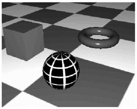
Figure 1
Since the scanline algorithm cannot display transparency and shadows, the ring is opaque.
You need the ray tracer to display the transparency. Although the raytracer is an independent program, it is controlled by MaxonCINEMA 4D in such a way that you don't notice it. Before that, MaxonCINEMA 4D saves the current document in a temporary file, since all scenes must be available on the hard drive for the ray tracer.
-
Start the ray tracer.
When the ray tracer has calculated the image (which takes a relatively long time), you will see the transparent ring in front of the ground. If you had difficulties understanding everything up to this point, you can also refer to the "Tutorial 1" scene supplied (see Figure 2).
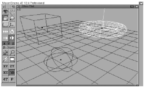
Figure 2
Until now, scanline algorithms and raytracers have always calculated their images on a quarter screen. However, you can also specify any other sizes. This can bring enormous time savings when reducing, because even with a resolution of "only" 160128 pixels (set image size), MaxonCINEMA 4D has to solve and calculate the overlapping problem and the brightness calculation for approx. 20000 points . On the other hand, if you calculate an image with the size of 8064 pixels, then these are only 5000 points, the image is therefore calculated four times faster.
-
Invoke the "Raytracing" function from the pop-up menu of the "Calculate image" icon while holding down the Shift key.
In addition to many switchable options, you can enter the resolution in the number fields, which can be chosen as desired. It is also possible to calculate in wide format with 320128 pixels or 800256 pixels.
Instead of entering the numerical values by hand, MaxonCINEMA 4D offers you preset resolutions. There are three fields for this: “Reading image”, “Middle image” and “Full image”. Full screen sets the resolution to full size. In addition, all options are activated. Fin click on “Middle picture” sets a quarter picture like we had before. Finally, "Test image" means that only a very small image is calculated. In addition, almost all options are deactivated so that the image is calculated as quickly as possible. When trying out how materials look on objects, you should always prefer this setting, because you can then see very quickly whether everything looks as desired.
-
Click on the "Test image" field. Exit the "Raytracing" window by clicking on "Start calculation".
Your settings were not only saved as with a click on "OK", but the ray tracer was also started.
After a short time you can see the scene with the cube, the ball and the ring again, but this time much smaller. Also, the ring isn't transparent this time, because your click on "Test Image" disabled the "Transparency" option.
-
If you want, you can now calculate the scene as a full screen with the ray tracer.
8. Working with hierarchies
-
Create a new document with a cone.
-
Call the "Manage Objects" function from the "Edit" menu. You will now see a window with two selection lists in which the names of all objects created so far are displayed.
When selecting objects, you have already learned the first difference between activating objects and sub-objects. This is followed by a detailed explanation of how objects can be structured hierarchically.
The principle of object management in MaxonCINEMA 4D is based on the possibility of combining objects into new objects, so-called object groups. This gives you a better overview and you can apply certain functions to several sub-objects at the same time. This procedure corresponds to working with the Amiga operating system. There you can, for example, also move or copy entire directories and do not need to duplicate file by file. Just like the Amiga operating system, MaxonCINEMA 4D not only offers you the possibility of combining objects in object groups, but also of removing them from these object groups.
Currently, only the names "Camera" and "Cone" appear in both lists. The "Perspective" camera is always present by default. Next to the cone is a small pictogram with a black arrow. This indicates that the cone is made up of faces. The black arrow is always displayed when an object contains further sub-objects.
-
Select the "cone" with a double click.
The contents of the cone object group are displayed. It contains the sub-object "Soil".
-
Click on the "Higher" field under the left selection list.
You are again one hierarchical level higher.
Next, you are supposed to make a copy of the cone.
-
To do this, click once on the name "Cone" and then on "Duplicate".
The name "Kegel.2" now also appears in the selection list.
-
Click once on the name "Cone". Then select the text entry field under the left selection list and change the name to 'Cone.1'. Leave the text input field with .
The two names "Cone.1" and "Cone2" can now be seen in the selection list.
Next you should create a new object group to group the two cones.
-
Click on "Axis" (An axis is an empty group of objects that does not consist of points or surfaces) . A new object named "Axis" appears.
-
Change the name from "Axis" to "Two Cones".
-
Move the mouse pointer to the name "Two Cones" (in the left selection list) and double-click.
The left list now shows the contents of Two Cones. Since there is currently no content, the list is also empty. The list on the right has not changed in the meantime and still shows the same thing.
-
Step out of the group of objects by clicking on "Up". The same list as on the right appears again. We now want to place the two objects “Cone.1” and “Cone.2°” in the “Two Cones” directory.
-
Move the mouse pointer to the name "Two cones" in the right list and double-click. The still empty list appears.
-
Select the object "Cone.1" in the list on the left.
-
Click on "Move".
You can see that the "Cone" object has moved from the left list to the right. It is now in the Two Cones item group.
-
Repeat the action for the object "Cone.2"
Both cones are now in the "Two Cones" directory. You can easily check this:
-
Double-click the TwoCone object in the left list. Immediately you will see the content, namely the two cones, just like in the right list.
Let's summarize again:
-
Double-clicking on an object group takes you into it.
-
A click on "Higher" lets you get out of this object group again.
-
With a click on "Move" you can move a selected object from one list to the other.
-
In the text entry field below a list, you can change the name of the selected object.
-
You can create new object groups with the "Axis" field.
-
The Duplicate field allows you to duplicate a previously selected object.
The "Manage Objects" window also offers you other helpful functions. You can save individual objects on the hard drive, for example because you can often use them in other scenes. In this way you can create a whole library of important objects. For example, once you have created and saved a chair, a table and a cupboard, you can access them again at any time.
-
Select the Two Cones object to save and click Save. The well-known "file selection" window appears.
-
Enter the path name under which the object should be saved. It is best to leave the name at "Two cones".
-
Exit the window by clicking the close icon.
You only see one cone in the document window because the two objects are on top of each other. Use the "Select object" function to select the "Cone.2" object and move it slightly on the surface.
-
Then use the "Select objects" function to select the "Two cones" object and move the object as you like. You can now see the advantage of a hierarchy: multiple objects can be moved at once.
9. The clipboard
One is often faced with the problem that one has laboriously created an object, for example a wheel of a car, and needs it four times. To do this, you can use the duplication function from "Administration" just described. But there is a much more elegant way, as the following section shows. MaxonCINEMA 4D has a so-called clipboard. This is internal storage where copies of objects — that is, bodies, lights, and polygons — can be temporarily stored. The clipboard is comparable to a drawer in which you put copies of important documents so that you can retrieve them at any time.
Probably the most frequently used function of the clipboard is "Copy" from the "Edit" menu. This allows you to create a copy of the active object. The copy is not visible, only stored internally. If you would like to call up this copy, you only have to select the "Paste" function from the "Edit" menu. An identical object immediately appears in the place of the previous active object, even if it has been deleted in the meantime. By calling up the "Paste" function again, you can have any number of copies appear on the editor's workspace.
-
Create a cube in a new document.
-
Call up the "Copy" and "Paste" functions from the "Edit" menu one after the other. The old cube is deactivated and a new active cube is immediately drawn over it.
-
Move the new object a bit so that the old cube becomes visible.
A slight modification of the "Copy" function is the "Cut" function. It basically does the same thing as above, except that the original object — of which a copy is placed on the clipboard — is deleted. You can use this function to delete objects, but you can be sure that the object is not completely lost, but is stored in the clipboard and can be retrieved at any time. This function is similar to cutting an image from a piece of paper and then placing that image in the paper tray.
To delete an object directly — without going through the clipboard — there is the “Delete” function from the “Edit” menu. The active object is deleted from the desktop and from memory. Calling up the "Paste" function now has no effect, since no copy of the previously deleted object has been made.
You can achieve the same by simply pressing the key or the key.
note
Of course, an object is only stored in the clipboard until a new object is copied or cut. This new object then displaces the old one from the clipboard
10. Undo mistakes
Hasn't it happened to you while working on the computer that you typed in a long text and accidentally deleted part of it? Then you must have wished for a function that undoes such mistakes. MaxonCINEMA 4D offers you this function. To do this, a copy of the active object is created internally (not via the clipboard) before you call an object-changing function. If you then made a change to the object that is not what you wanted, all you have to do is call up the "Undo" function from the "Edit" menu and the active object will appear again in its original state. "Undo" only refers to functions that change objects, but not to functions that move the editor's surface or enlarge the visible section.
-
Generate a ring
-
Select the "Wrinkle" function from the "Tools" menu. This wrinkled her ring irregularly.
-
Choose "Undo" from the "Edit" menu.
You see the originally smooth ring in front of you again.
-
You can now undo "Undo" yourself by calling the function again. The crumpled ring then reappears.
-
Calling "Undo" again makes the smooth ring appear again. This can be repeated as often as you like, even if you change the view or change the editor section in between.
11. Material design
Now that you've learned how to use the supplied library of materials and how to calculate scenes, it's time to create your own materials.
-
Close all previous documents and create a new one. Create a sphere and adjust the camera in the "Perspective" view in such a way that the sphere appears centered in the middle of the picture and has a size that almost fills the frame.
-
Go to the Manage Materials feature.
-
Click on "New" to create a new material.
To the right of the list you can edit the new material. There is a button for all properties of the material such as color or transparency. Depending on which button is currently activated, the values of the sliders and fields to the right of the buttons refer to this set property.
-
First change the name from "New" to "Yellow"
The most important property, the color, is at the top left. If you activate the button for the color, you can adjust the hue with the three sliders. Play around with the sliders to get a feel for the different color settings.
Alternatively, you can also enter the color components manually in the fields next to the slider.
-
Set a hue of 100% red, 100% green, and 0% blue using the sliders or numeric input. This results in yellow.
Your new yellow material is now in the material list.
-
Close the window.
-
Assign the new material "Yellow" to the sphere with the "Select Material" function and look at the result in the scanline algorithm. You will see a dull yellow sphere.
The next step is to modify the material you just created. Of course you can now use the "Manage materials" function again. But it is even faster with the "Edit material" function. If a material has already been assigned to the currently active object, a window appears without a selection list in which you can immediately edit the material parameters.
-
Call the "Edit Material" function.
You will now see the 'Edit Material' window in front of you.
-
Set the "Gloss" text entry field to 40% and exit the window with "OK". Consider the object again using the scanline algorithm.
This time the yellow ball has received a highlight.
By experimenting with the many parameters in the Material window, you can create a variety of interesting materials. You can also save these for later use. To do this, use the "Save" or "Save all" fields in the "Manage materials" function.
12. Textures
Even the most sophisticated settings for the material parameters of a surface do not result in the realistic images you are used to from TV commercials. The surfaces of objects only get the right pep when they are covered with textures (images). For example, you can use an image of the Coca-Cola logo to turn a boring top hat into a Coke can in seconds. Or you put a picture of the earth's continents on a sphere. Immediately you get a plastic globe.
As you have already seen, there are parameters such as color, transparency and mirror ability. These determine the appearance of all points on a surface. You could just as well enter them individually for each point on the surface. Textures allow you to do this. For example, you can use a paint program to paint white lettering on a black background. If you use this image as a color texture, the color from your image will be used instead of a uniform color for the entire surface. So you can later see the lettering on the object. The object has a white color wherever the lettering is located, otherwise it is black.
On the other hand, if you use the image as a transparency texture, dark areas of the image will be interpreted as more opaque than light areas. As a result, the object becomes completely opaque in all places where there is no lettering. On the other hand, you can see other objects behind it shining through the lettering. Likewise, a specular texture controls the specular properties of the surface depending on the color in the image. Of course, you can also combine the textures mentioned above.
With all of this, however, the question arises as to how MaxonCINEMA 4D brings the images to the surface of your objects. After all, objects can have very different surface shapes, from a flat square to a round sphere to a jagged fractal. Since it would be too time-consuming to determine the exact shape of the surface for each object and then place the texture on it, MaxonCINEMA 4D provides you with three important projection types. In the simplest way, area projection, the image is projected or placed completely flat onto the object in question - regardless of whether it is a flat or a round object. The flatter the object, the more undistorted the image will be projected. You can imagine the surface projection as with the slide projector. The slide - in our case the texture - is thrown onto an arbitrarily shaped object.
On the other hand, if you have an object that is more cylindrical in shape, for example a can or a vase, then the second type of projection is recommended, the cylindrical projection. It bends the texture once around the object and projects it inward.
The previously mentioned globe is generated with the spherical projection. It bends the texture in two directions around the object, eventually becoming spherical and projecting inward onto the object.
But enough with the theory. It's best to try it out for yourself.
-
Use the sphere from earlier and go to the Manage Materials feature.
-
Create the new material called "Earth Material".
-
Activate the "Color" button and click on the icon to the right of the text input field for the texture.
The file selection window appears.
-
Select the image named 'Earth' which is supplied with MaxonCINEMA 4D.
MaxonCINEMA 4D now displays the name of your image with the full path in the input field.
-
Click on the "Show" button.
MaxonCINEMA 4D immediately loads and displays the image. You see a map of the continents of the earth.
-
Click anywhere on the image to stop viewing.
An information window now appears in which MaxonCINEMA 4D displays the size of the image and the color depth.
You have now set a color texture for the "Earth Material" material.
-
Exit the window and assign the new material to the sphere.
Now it is a matter of telling MaxonCINEMA 4D how the texture is to be placed on the object.
-
Click on the "Texture" icon on the main bar.
The view changes immediately. You can now see a mesh with several grid lines on the sphere. This grid represents the texture. With the actions "Move" or "Scale" you can change the texture as you wish.
-
 First open the texture bar with the corresponding function from the "Window" menu. There are useful functions for editing textures. From there, click on the "Surface Texture" icon.
You have now informed MaxonCINEMA 4D that you want to project the image flat onto the sphere.
-
Now click on the "Scale" icon on the main bar and adjust the size of the texture down to about 1/4 in the X direction and 1/2 of the original size in the Y direction.
You have now scaled down the texture. You can see this by the fact that the texture with the fine grid lines has shrunk while the original border has remained the same.
-

 Click on the "Move" icon on the main bar. As with moving objects, you can now move your texture with the mouse. Again, you can disable the "X" or "Y" icon and then move the texture in either direction only. The "Z" symbol currently has no function because a flat image has no third dimension. With a right-left movement of the mouse you control the X-position of the texture, with an up-down movement the Y-position.
 -
Click on the 'Edit Texture Axes' icon on the main toolbar. Now you can move, rotate and scale the axes of the texture system along with their limits in three dimensions. Please try this.
-
 Now click on the "Cylinder Texture" icon in the texture bar.
Instead of the flat boundary, a cylindrical boundary now appears, on which the texture can be seen with its grid lines, filling the format. `
-
Resize the texture with "Scale" after clicking the 'Edit Texture' icon on the main bar again.
-
Activate the "X" icon. Disable the "Y" and "Z" symbols.
-
Now click on the "Move" symbol and move the mouse while holding down the left mouse button.
You can watch the texture move around the cylinder without the cylinder itself moving.
Let's summarize:
You are free to choose which of the three projection types (area, cylinder or sphere) you want to use. You can optimally adapt the texture to your object. In addition, you can use the "Texture Axis" icon to set the direction of the texture and position the texture precisely. The fine grid shows the places where the color, transparency or mirror texture will appear later in the image calculation. An example of an application is a label on a soda bottle.
-
 Click on the "sphere texture" icon.
Now the texture appears wrapped around a sphere again.
-
Call the scanline algorithm.
If you did everything correctly, now you can see the sphere with a picture of the continents of the earth.
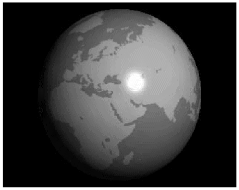
Figure 3
If you leave the scanline algorithm and move the camera appropriately, you can view the globe from all sides.
-
Set the texture size to about 1/4 the original size.
Now the formerly format-filling texture only occupies a small part of the sphere's surface.
-
Restart the scanline algorithm.
The sphere is displayed again, but this time it is covered with the texture several times. MaxonCINEMA 4D automatically attaches the texture to each other several times, as long as you have not prohibited the program from doing so with the "tile texture" icon in the texture bar.
If you had trouble following this section, you can also just load the "Tutorial 2" scene.
13. Polygons
In addition to the basic objects, you can also create complicated organic shapes and objects with polygons.
These polygons represent nothing more than a contour that you can rotate around an axis in three-dimensional space to obtain an object—say, a vase. But you can also place objects along such a polygon, or move a polygon along a polygon to get a tube or, or... there are no limits to your imagination.
MaxonCINEMA 4D offers you pre-made polygons.
-
 First close all documents and create a new one. Call the "Circle" function from the "Objects/Polygons" menu.
The outline of a circle appears in the document window. This contour (polygon) behaves like a normal object with faces, i.e. you can move, rotate or modify it in the same way.
-
Now create a "Line" with the function of the same name from the "Objects! Polygons menu.
You should now get to know a function that allows the contour of the circle to run along the line. that a ring-shaped hose comes out.
-
 Invoke the 'Path Object' function from the 'Objects/Polygon Objects' menu while holding down the Shift key.
In the 'Path Object' window you can specify which polygon should be used as a path and which one you want to run around the path as an outline.
-
Click on the 'Path' field in the window. The object selection window appears. Select the "Line" polygon.
Now the name of the currently selected polygon is displayed next to the 'Path' field. You now have to specify which contour should be moved around this path.
-
To do this, click on “Select contour”.
This time a window with two lists appears. All available polygons are displayed in the list on the left, and those polygons that MaxonCINEMA 4D should use as contours are displayed in the list on the right.
-
Check the "Circle" polygon in the left list and click "Move" to add it to the right list.
Exit the window with "OK" and also the window for path objects with "OK".
MaxonCINEMA 4D now places the Z-axis of the contour on the polygon line of the path and shifts the contour 10x until a tube is created. It is best to move the camera around the newly created object in the "3D" view so that you can see the result clearly.
Of course, there are a number of parameters in the path objects window that you can play around with. For example, you can increase the number of divisions from 10 to 20 to make the hose finer, or even add caps to the front and back ends of the hose. See the reference for more details.
As already mentioned, you can use polygons to conjure up three-dimensional objects on the screen simply by calling a function that interprets the polygon as the contour of an object and rotates it around an axis in space. So that you can try this out quickly, the "Scenes" directory already contains a prefabricated polygon called "Vase contour".
-
First close all documents and call up the "Open" function. Then load the supplied polygon "vase contour".
You can now see the outline of a vase in the XY plane on the workspace.
-
Call the "screw object" function
Shift-click from the Objects/Polygon Objects menu. This function rotates polygons (contours) around their Y object axis.
In the window you can specify which polygon you want to use as the contour, by how many degrees the contour should be rotated around the Y-axis and in how many steps this should happen.
-
Click on "Select contour". As before, a window with two lists appears.
-
Highlight the name "Vase Contour" in the list on the left and click "Move".
-
Enter the value 100 in the "Subdivisions" input field and exit the window with "OK".
-
Also exit the "Screw object" window with "OK".
MaxonCINEMA 4D now immediately calculates the three-dimensional body and displays it on the workspace. It is best to look at it in the 3D view. Then you can see the vase shape of the object very nicely.
In this way you can create any rotationally symmetrical objects. In addition to the "screw object" function, there are a number of other functions that create objects from polygons. For example, several polygons can be assembled layer by layer to form an object. But all this works just as easily as in the example of the vase just described. For these functions, please see the reference where they are fully documented.
At the end of this chapter you will learn how to design polygons for your own creations.
-
Open a new document, create a line with the function of the same name from the "Objects/Polygons" menu and switch to the "XY" view.
-
Click the "Edit Points" icon on the main bar.
MaxonCINEMA 4D now draws all points of the polygon. However, the line has only two points. If "Move" is set, you can grab the points directly with the mouse and move them to a new location.
-
To do this, place the mouse pointer on one of the two support points of the polygon and keep the left mouse button pressed. While still holding the button, move the mouse.
You can see the connecting line attached to the point following the vertex and your mouse pointer.
As soon as you release the left mouse button, the support point is placed at the new location. You can easily "grab" points and move them afterwards.
Want a few more points? No problem, all you have to do is click on the appropriate spot and press the key at the same time. The rule is that if you click near a connecting line between two vertices, the new point is inserted between the two vertices. Otherwise, the new point is simply appended to the last point of the polygon.
Did you accidentally enter one point too many? Also no problem:
-
Click on the relevant point to activate it and press the
key. The point disappears.If you want to edit several points at the same time, you can do this by clicking the points one by one while holding down the Shift key. Then all clicked points will be activated at the same time. Alternatively, you can also draw a frame around the relevant points by enclosing the desired points while holding down the key.
Let's summarize again:
-
Points are activated by clicking on them.
-
You can select multiple points by holding down the Shift key.
-
You can frame multiple points at once by holding down the key.
-
Open the "Information" window and set the "'Parameter" page. There is the "'Polygonart'" field. Set the interpolation type to "Cubic".
-
Create a flower-shaped polygon using the "Flower" function from the "Objects/Polygons" menu and click on the "Edit View" icon.
-
Open the information window and set the "Parameter" page.
The current interpolation type (here it is cubic) is displayed in the "Polygon type" field.
-
Change this from Cubic to Linear.
Immediately, the flower changes into something that looks more like a gear than a flower.
By combining the different types of interpolation with appropriately set support points, you can create any conceivable shape, both for use as a contour or as a path along which a contour is moved.
This brings us to the end of the tutorial. You now have an insight into the most important functions of MaxonCINEMA 4D. All other functions are described in detail in the reference
We hope you enjoy your further work with MaxonCINEMA 4D!