68 KiB
- Basics
- 1. Document
- 2. Menu
- 3. Toolbars and windows
- 4. Input window
- 5. Warnings
- 6. Coordinate Systems
- 7. Grid
- 8. Units and Functions
- 9. Angle system
- 10. Camera model
- 11. Objects
- 12. Points, Edges and Faces
- 13. Polygons
- 14. Light model
- 15. Colors
- 16. Materials and Textures
- 17. Smoothing
- 18. Image output
- 19. Working method
- 20. Animation
Basics
Important basics for understanding the program are explained here. Please read this part as carefully as possible.
1. Document
MaxonCINEMA 4D works document-oriented. A document consists of the data for the scene — that is, objects (bodies, polygons, lights, camera), materials, and the scene environment. In addition, certain settings, e.g. for image calculation, are also included. A document can be saved as a whole on hard disk.
The menu and toolbar functions only affect the currently active document. A document is activated by clicking in the associated document window. To bring a document to the front, click the document's bottom window border.
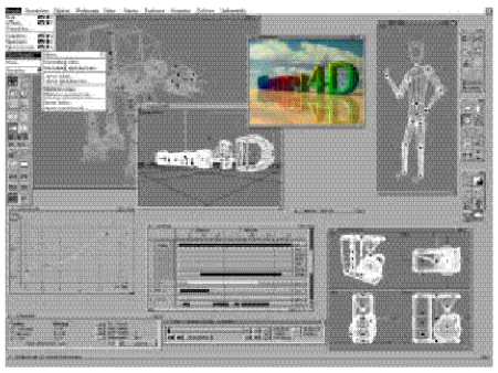
Figure 1
In Figure 1 you can see a typical example of what the desktop looks like. Four document windows, in which the objects are displayed, take up the largest part. In addition, there are several toolbars on the interface. On the left you can see the main bar, which is always present and contains the most important program functions. All other toolbars can be opened or closed as needed. They contain functions that are used less often, for example for placing textures or editing individual points. Windows and toolbars can be moved, enlarged, closed or clicked behind other windows as you wish.
MaxonCINEMA 4D distinguishes between a workspace with eight or more colors and a workspace with four colors or the workbench. If only four colors are set on the desktop or the workbench is used, then all documents are drawn in the background color. Active objects are displayed in white, inactive objects and the grid in black. All places where active and inactive objects overlap are problematic. A disturbing shade of blue appears there. You can eliminate it by changing the fourth screen color to a light gray. On the Workbench you use the Preferences program "Palette" for this, on a four-color screen you can use the "Editor..." function from the "Project'Preferences" menu. Working in the editor is faster with four colors than with eight or more colors. On the other hand, there are no problems with the overlapping of active and inactive objects with eight or more colors. The documents have a more elegant look and are drawn in a dark gray tone. Active objects are shown in white, inactive objects in grey. The grid still has the
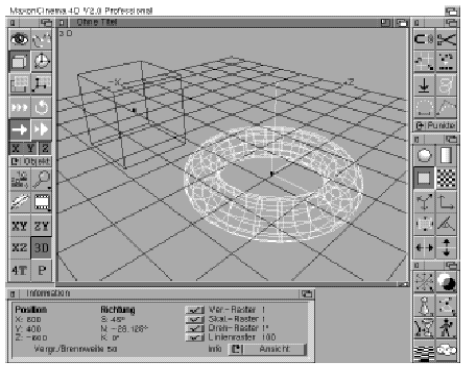
Figure 2
Color: Black. You can freely set the color of the active objects without affecting the appearance of the desktop.
Figure 2 shows how MaxonCINEMA 4D looks with four colors or on the workbench, while Figure 3 shows how it looks with more than four colors.
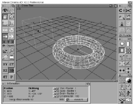
Figure 3
You can freely select the view for each document. A document's scene can be displayed in one of the three parallel views (Floor Plan, Elevation, Side Elevation), in one of the two perspective views (Editor Camera or "Perspective'" camera), or in the four views Floor Plan, Elevation, Side Elevation, and Editor Camera simultaneously . The latter representation is particularly recommended when a good overview is important. This view is particularly useful for users with graphics cards and large monitors (17 inches or more). However, the image construction is slower than with the individual views, since four cracks have to be drawn at once.
In MaxonCINEMA 4D you have the unique opportunity to interrupt the image build-up at any time. You no longer have to wait minutes for the editor to set up a complex scene, you can continue working immediately — even after a part of the objects has been drawn. The screen build-up is automatically interrupted when you select a new function.
2. Menu
In the menu you will find all functions that are not in the main toolbar. Since MaxonCINEMA 4D guarantees mode-free working, you can call up all functions at any time. Also, there is only one menu that applies to all windows.
There are three dots behind the names of some menu items. An example of this is the "Save as..." menu item. The three dots mean that after the function has been called, an input window will appear in which you can enter various information about the function before it is started. On the other hand, menu items without the three dots cause a function to be executed immediately.
However, since there are also functions in MaxonCINEMA 4D where you can — depending on your requirements — provide more detailed information in a window or start the function immediately with the preset values, the “•” symbol was introduced. Menu items such as “Rewind • ’ marked with this symbol offer both options.
If you call up such a menu item with the mouse in the usual way, the function is started immediately — as with menu items without dots after the name. However, if you hold down the shift key while selecting the menu item, a window appears, just like with functions with the three dots. So by pressing the Shift key you decide which of the two possibilities will be executed. The Shift key is not only important when making selections with the mouse, but also when making selections using a keyboard shortcut.
You can call up all menu functions by pressing a key or by pressing a key in connection with or . If you are working on the operating system version 3.0 or higher, all shortcuts are displayed in the menu.
Professionals like to work with such keyboard shortcuts because functions can be called even faster. You have to memorize a few abbreviations for this, but this happens automatically if the program is used frequently. The summary table for all keyboard shortcuts can be found in the appendix.
3. Toolbars and windows
In order to be able to work quickly with MaxonCINEMA 4D, there are various toolbars. The main toolbar is always visible and cannot be closed. It contains the most frequently used editor functions.
However, you can use other toolbars. The corresponding names are available in the "Window" menu, for example "Point bar" or "Texture bar". When you select such a name, the corresponding bar will appear on the screen. In the menu, the name is marked with a tick.
You can close all toolbars except the main toolbar at any time, either by selecting the checkmarked name in the menu again, or by clicking the close icon in the top left corner.
Clicking on the close icon on the main toolbar corresponds to selecting the menu item "End" in the "Project" menu.
Note
All functions present in the menu behave the same as the equivalent functions of the toolbars.
Just as you can evoke different reactions in the menu for all functions with the ending “•”, some symbols also have different meanings. For example, if you left-click on the "image calculation" symbol, the entire scene is immediately calculated and displayed in the selected quality level. The same action with the right mouse button first brings an input window onto the screen in which you can enter differentiated information about the function before it is started.
Some symbols have a small black triangle in the bottom right corner. It means that there are other functions hidden behind the symbol. If you click on it, a drop-down menu opens with further options. To cancel the selection, you must move the mouse outside the image area of the pop-up menu and then release the left or right mouse button.
In addition to the toolbars, you can also open a so-called “Information” window. It displays important data about the currently activated objects or functions. Since there is not enough space in a complex editor like MaxonCINEMA 4D to display all the data at the same time, the data is divided into several thematic groups. You can use the "Info" field in the "Information" window to determine which of the groups is currently being displayed.
MaxonCINEMA 4D's ability to work non-modally is unique. For example, if you move an object in the document window, you can simultaneously observe the change in coordinates in the "Information" window. But the special thing about it is that it also works the other way around. You can change values directly in the "Information" window that have an immediate effect on the document.
But that's not all: You can even enter entire formulas and functions. For example, if you want to scale an object to 2.5 times its size, just type "*2.5" and you'll get the result you want.
- You can find more detailed information about the possibilities of formula evaluation in chapter 8 "Units and functions".
When you have found an arrangement of windows and toolbars that suits your taste (layout), you can save it. This arrangement is then set automatically when the editor is started, and you can immediately start working with your favorite environment. It is also possible to save several different layouts, which can then be accessed as required.
4. Input window
For many functions, an input window appears in which several values must be entered. It's annoying to constantly have to take your hands off the keyboard just to activate the next input field with the mouse. In MaxonCINEMA 4D it is therefore possible to jump from input field to input field by pressing the tab key. You can also jump backwards by holding down the Shift key at the same time. You can also use the up and down arrow keys instead of the tab key.
Almost all fields have one letter of the field name underlined. If you press this letter on the keyboard, the corresponding field will be activated. However, this only works if an input field with a cursor is not currently active somewhere in the window. You can deactivate an input field by pressing the key.
You can leave each input window with .
Depending on the context, values for degrees or units such as "cm" or "km" are required in the input fields for numerical values. You can add these units to the numerical values or omit them entirely, in which case the default basic unit will always be used. Entries such as “12cm”, “O.12 m”, “12E-6km”, “120mm” or even “120” are identical if the basic unit was set to “mm” in the default settings (see also Chapter 8 “Units and functions').
If you make an incorrect entry - be it that you entered the wrong unit in a numeric field or that the entered values are outside the permissible range - you will be automatically informed when you leave the window that the entry was wrong and in which range the correct value is This makes it impossible for any erroneous values or settings to come about.
Studies have shown that the values of an input window are usually only slightly modified from function call to function call (e.g. the name of an object). Therefore, MaxonCINEMA 4D has the ability to save values of an input window once they have been entered. When you reopen the input window, you will then see the previously entered values instead of the default values.
5. Warnings
Before executing functions that cause something irrevocable, MaxonCINEMA 4D will always ask you if you really want to do this. A window appears in which you can either confirm or cancel the selected action. Experienced users who do not need such queries can switch them off in the preferences.
Some functions use a lot of memory. If there is not enough storage space, MaxonCINEMA 4D will alert you. You then have the option to free up memory, for example by closing other programs, or you can cancel the action.
If MaxonCINEMA 4D runs out of memory to display the warning window, a so-called "Guru'" message is issued, which requires significantly less free memory. However, if there is not enough memory for this either, the action is aborted with a flashing screen.
6. Coordinate Systems
MaxonCINEMA 4D works with different coordinate systems. The most important system is the world coordinate system (Figure 4). It is three-dimensional with the spatial axes for the X, Y and Z directions. The X-axis extends from left to right, the Y-axis from bottom to top and the Z-axis from front to back (if it is looking in the Z direction).
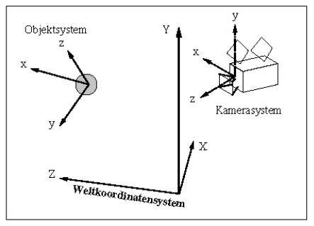
Figure 4
Note
The arrangement of an object in relation to its object axes is important for many functions. In MaxonCINEMA4D, the Z-axis is defined as the so-called "Show" axis. With the "Show" axis, for example, an object follows a path or the camera always looks at the scene along its "Show" axis.
The world coordinate system is - in contrast to the right-handed coordinate systems commonly used in mathematics (where the Z-axis would point towards the viewer) - a left-handed system. This was chosen on purpose, since most editors for three-dimensional objects use such a system.
In addition, each object has its own object coordinate system. This system is represented by three axes and the origin in the active object. In the case of inactive objects, only the origin is visible for reasons of clarity.
The object coordinate system can move with the object or be changed independently of the object.
Camera coordinate system is another term for "object coordinate system of the camera".
All objects in a scene that are displayed on the screen are transformed into the screen coordinate system of the screen according to a mapping rule (two-dimensional parallel mapping or perspective mapping). The origin of this system lies in the center of the document window in which the scene is displayed. The X-axis points to the right, the Y-axis up and the Z-axis backwards, so to speak into the monitor (Figure 5). The screen coordinate system is independent of the currently selected view (front, side, top, etc.).
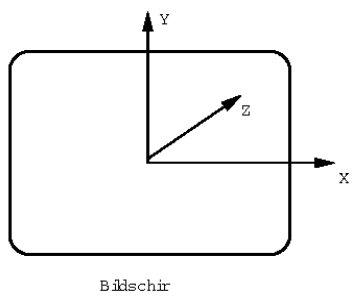
Figure 5
7. Grid
MaxonCINEMA 4D knows different types of grids for precise work when positioning and rotating objects.
Note
In the perspective views, the line grid is only displayed in the XZ plane around the origin of the world coordinate system. Otherwise, too many lines would confuse you and block your view of the rest of the scene.
The most important grid is the line grid. It appears in the drawing in the form of several parallel vertical and horizontal lines and is intended as an aid to better orientation. You can freely adjust the spacing of the lines. The line grid disappears when the grid points are too close together.
Even if you have switched on the line grid, it is often not easy to position objects exactly on the grid points of a grid. A small mouse movement is enough and the object to be moved jumps from position 10,374 to position 10,694, for example. To prevent this, there is the so-called shift grid. It is not displayed using lines on the workspace, but means that you can only move an object to positions that are a multiple of the set value. It is no longer possible to move objects freely.
Note
The sliding grid can be used independently of the line grid. For example, you can use a line grid of 100 units while the scroll grid is 13.5 units. However, it makes sense if both grids overlap or are a multiple of each other. You then have better visual control.
For example, if you enabled a panning grid of 10 units, the object will jump from its current position by 0.0 units, 10.0 units, 20.0 units, and so on. So an object at position 5.6 would jump to positions 4.4, 5.6, 15.6, and so on.
You can also achieve a compromise between free panning and exact positioning by setting very small values, such as 1 unit, for the panning grid. The coordinate values always remain integers. However, you can still move the object relatively freely.
If you create and edit very regularly shaped objects, you will appreciate the displacement grid. An architect can thus very quickly enter the floor plan of a house, since most walls are arranged at right angles and their size is a multiple of a certain basic length (e.g. brick 30cm). The walls can then be precisely adjusted to each other with a sliding grid of 30 cm.
Note
Like the shifting grid, the scaling grid is independent of the line grid. You can see it in the "Information" window
The shifting grid also has an important function: it ensures that newly added objects or points always appear on grid points.
The scale grid behaves similarly to the translation grid. A value of 10 units means that an object can only be enlarged or reduced by 10 units or a multiple thereof.
Note
Just like the sliding grid, the rotary grid is independent of the line grid. You can turn it on in the "Information" window.
Finally, there is a fourth grid, the rotation grid, whose value is entered in degrees. A value of 10° allows an object to be aligned in 10° increments. This can be very useful for positioning light sources or cameras, for example.
8. Units and Functions
MaxonCINEMA 4D allows the use of metric units and measurement systems. In the preferences, you can define a base unit in which the numerical values are always displayed.
However, numbers can be entered in other units at any time by putting the appropriate unit after the number. For example, the specifications 2 mm and 0.2 cm are equivalent.
MaxonCINEMA 4D knows all the important German units of length such as nm (nanometer), um or um (micrometer), mm (millimeter), cm (centimeter), dm (decimeter), m (meter) and km (kilometer). Alternatively, input in pixel units (specification without unit) is also possible.
Various units are available for animation. First, there is unit “B”.
Note
- Expressions can be nested as required.
- It doesn't matter if you write upper or lower case
- Degrees do not have to contain a degree sign (°). If it is missing, it is added internally.
- You get the number e (Euler's number) with the term Exp(1)
- The brackets (, [ and { can be used and mixed as desired
- All trigonometric functions work in degrees
- Units can be used freely, e.g. "5km+3cm-14μm"
- Since the "μ" is difficult to reach on the Amiga keyboard, you can also enter a "u" instead
- The formula can be up to 128 characters long
- The entries for the object position etc. are not gridded — regardless of whether the translation grid is active.
For example, you can type "510 B" and MaxonCINEMA 4D will interpret this value as frame 510.
On the other hand, there is the extended notation. It has the form "min:sec:frames". For example, "3:20:14" means you mean the time "3 minutes, 20 seconds, and 14 frames". The last value does not specify hundredths, but frames, since you may have defined a rate of 25 frames per second, for example. In this case, "images" can only have values between 0 and 24.
In the extended notation, the minutes can be omitted (e.g. "15:14"). The first value then indicates the seconds, the second the images.
If you enter a number without a unit, then it depends on the "animation unit" in the editor settings (reference V.1.7.1), how it is evaluated. If "animation unit" is on images, then the entered value is used as an image number interpreted, otherwise it stands for the seconds.
MaxonCINEMA 4D contains a parser routine. It allows you to enter entire formulas. For example, you can type "*1.8" into an input field. MaxonCINEMA 4D then multiplies the existing value by 1.8. Mental arithmetic or the use of a pocket calculator are no longer necessary. The table below lists all functions and identifiers that MaxonCINEMA 4D knows.
| Symbol | Function | Example | Result |
|---|---|---|---|
| + | Addition | 4+5 | 9 |
| - | Subtraction | 4-5 | -1 |
| * | Multiplication | 4*5 | 20 |
| / | Division | 4/5 | 0.8 |
| Sqr() | Square | Sqr(4) | 16 |
| Sqrt() | Root | Sqrt(4) | 2 |
| ^ | Power | 2^3 | 8 |
| Sin() | Sine | Sin(30°) | 0.5 |
| arcsine() | Arcsine | Arcsine(0.5) | 30° |
| cos() | Cosine | Cos(60°) | 0.5 |
| Arccos() | Arccosine | Arccos(0.5) | 60° |
| Tan() | Tangent | Tan(45°) | 1 |
| Arctan() | Arctangent | Arctan(1) | 45° |
| Rad() | Conversion to radians | Rad(180°) | π |
| Deg() | Conversion to degrees | Deg(pi) | 180° |
| Log() | Common logarithm | Log(100) | 2 |
| Ln() | Natural logarithm | Ln(100) | 4,605 |
| Exp() | Exponential function | Exp(4.605) | 100 |
| Abs() | Absolute value | Abs(-2) | 2 |
| Frak() | Decimal part | Frak(1.234) | 0.234 |
| Int() | Digits before the decimal point | Int(123.4) | 123 |
| pi | Identifier for π | pi | 3.141592654 |
| (...), [...], {...} | Bracket | 4*(3+2) | 20 |
| E | exponent | 4E2 | 400 |
9. Angle system
In addition to position and size, an important parameter for describing an object in three-dimensional space is its position. There are many ways to indicate this location in space. MaxonCINEMA 4D uses the so-called Euler angles for this. In mechanics, these angles are often used to describe rotating systems. At the same time, however, they are an excellent approximation to the human approach when describing the position of an object in space.
Note
An object is always first rotated by its pan angle, then by its tilt angle and finally by its tilt angle.
Euler's angles consist of a triple of angles.
The first angle is the so-called pan angle, which rotates the object around its Y-axis. If the observer looks perpendicularly at the Y-axis so that the arrow on the axis is pointing in the opposite direction, the rotation is in a mathematically positive direction (counterclockwise) (Figure 5).

Figure 5
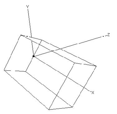
Figure 6
The second angle is called the tilt angle and rotates the object around its X-axis (Figure 6). Finally, there is the tilt angle, which rotates the object around its Z axis (Figure 7).
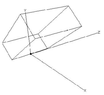
Figure 7
The combination of pan, tilt and tilt angles allows you to describe any position of an object. See Figure 8.
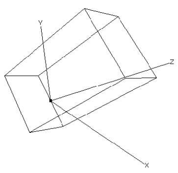
Figure 8
You combine all three angles with a pan angle of 30°, a tilt angle of 60° and a tilt angle of 45°.
All three angles are independent of each other. If you only change the inclination, the tilt or pan angle will never change.
10. Camera model
MaxonCINEMA 4D uses two different synthetic cameras to generate realistic scenes.
The editor camera is exclusively responsible for the construction of the objects in the editor. The "Perspective" camera is independent of this. It can display a different image section than the editor camera. The "perspective" camera is used for image calculation.
The separation has been made so that you can view the scene undisturbed. Driving around the scene with the editor camera will not destroy a spectacular shot of the "Perspective" camera.
In order to be able to display objects, MaxonCINEMA 4D projects them onto the screen of your computer in a central perspective. The objects are shown from the point of view of a synthetic camera. MaxonCINEMA 4D uses the camera coordinate system to clearly define the position and orientation of the camera.
Note
The editor camera is not displayed in the 'Perspective' view because it is exactly in the film plane.
The coordinate system of a camera is always such that the X and Y axes span the focal or film plane. The Z axis indicates the direction in which the camera "faces" and represents the scene in the editor. In the editor, the "Perspective" camera is represented as a cuboid with two film spools and a lens (Figure 9).
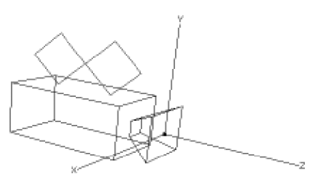
Figure 9
As in reality, the cameras in MaxonCINEMA 4D have imaging lens systems. You are free to choose which lens you want to use. MaxonCINEMA 4D allows you to specify the focal length of the lens.
Small focal lengths correspond to wide-angle lenses and allow a good overview of a scene. However, they also distort the objects, which is particularly important with extremely short focal lengths of the fisheye lens (Figure 10).
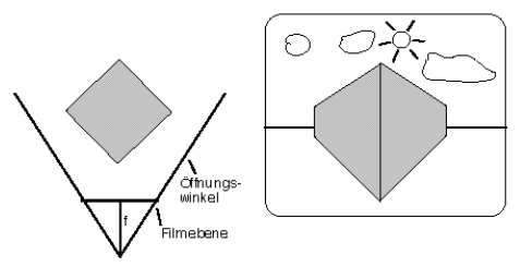
Figure 10
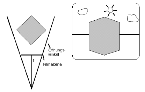
Figure 11
Large focal lengths, on the other hand, correspond to telephoto lenses. They only depict a small section of the scene, since they can only cover a small solid angle (Figure 11). On the other hand, significantly more details can be seen and the objects are hardly distorted. With extremely long focal lengths, the perspective depth impression is completely lost, since the perspective image changes into a parallel projection.
| Lens | Focal Length |
|---|---|
| Fish eye | 20mm |
| Extreme wide angle | 28mm |
| Wide angle | 35mm |
| Normal | 50mm |
| Portrait | 85mm |
| Tele | 200mm |
| Telescope | 1000mm |
11. Objects
Each object in MaxonCINEMA 4D is either a flat body, a sphere, a polygon or a light source. In addition, there are the objects ground, sky and "perspective" camera, each of which can only exist once.
Every object has an object coordinate system. The origin of this coordinate system is shown as a small black square. The three axes of the object coordinate system are also drawn for the active object.
You can easily activate the objects by clicking on the origin of the desired object. If an object is selected with the left mouse button, it is activated completely with all sub-objects. If you click with the right mouse button, only the object itself (without sub-objects) is activated.
The active object can also be selected using the 'Select object' function from the 'Edit' menu (s» Reference V.2.6).
You can combine multiple objects into new objects. All objects except ground, sky and perspective camera can be structured hierarchically.
Note
Objects with sub-objects are also called object groups in the following.
Otherwise, any object can have one or more sub-objects. For example, the object "car body" can have the sub-objects "left door" and "right door" (Figure 12). If the "car body" object is selected, all sub-objects are automatically selected as well.
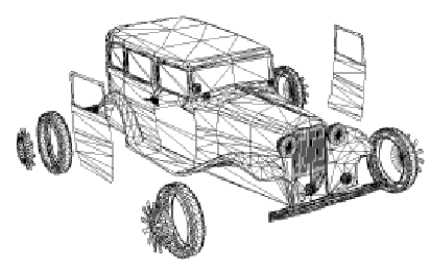
Figure 12
When selecting, you can determine whether you want to select an object as a whole (click with the left mouse button) or the object alone (click with the right mouse button). All object processing functions evaluate this information.
Note
When objects are mentioned in the following text, all types such as bodies, light sources, polygons, etc. are meant. The explicit mentioning of "body" always means that the context refers to the property of the body, ds flat object or sphere.
Because object groups combine objects into a larger unit, they are a suitable means of structuring large amounts of objects. This is particularly important for functions such as moving objects. By grouping objects, it is possible to move both individual objects and entire groups of objects at once. Otherwise each sub-object would have to be moved individually by hand.
The hierarchical object structure is an important prerequisite for professional work with three-dimensional objects. Especially in the case of animation, you can no longer do without hierarchy. Figure 13 shows an example of a hierarchical structure. The "Body" object contains the sub-objects "Left Door", "Right Door", "Tire 1", "Tire 2", "Tire 3" and "Tire 4". It therefore forms an object group. Each tire object is also an object group and contains the sub-objects "rims" and "rubber".
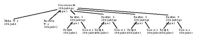
Figure 13
12. Points, Edges and Faces
Each body in MaxonCINEMA 4D consists of a certain number of faces. Faces can be either triangles or squares. Squares have the advantage that they take less time to calculate the image. All imaginable shapes and surfaces can be assembled with these two elements.
The vertices of the surfaces are connected by lines — the edges. A single triangle has three edges and a single quadrilateral has four edges.
In MaxonCINEMA 4D, you have the option of subsequently processing entire areas as well as individual edges or points. It is no problem to construct a completely new object or rotate a point cloud from several individual points.
You can even load an ASCII file with point coordinates, for example from a 3D scanner, and use it as a basis for defining triangles (Reference V.5.2.8).
13. Polygons
Polygons are an extremely important and powerful tool in MaxonCINEMA 4D. Not only can they be used to sculpt complex objects in seconds, but they can also be used to define motion paths when animating objects.
Polygons are primarily a sequence of three-dimensional vertices connected by lines. In addition to the direct connection of the support points — one also speaks of interpolation here — there are other types of polygons in which the interpolation between the support points does not take place in a straight line, but through a curve. Such polygons have a smooth curve without corners and jumps.
There are five different types of polygons: Linear, Cubic, Akima, B-Spline, and Jump.
- Probably the simplest type of polygon, Linear connects the vertices that define the polygon with direct connecting lines (Figure 14). You can use these polygons to create angular objects or to simulate choppy motion during animation.
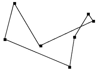
Figure 14

Figure 15
- The cubic polygon type creates a smooth curve progression between the vertices, whereby the interpolated curve always goes exactly through the vertices. It tends to overshoot on tight bends. You can see this in Figure 15 with the cubic interpolation at the two points on the top right. The curve extends further to the upper right than is actually necessary. This becomes particularly clear when you compare this curve section with the same section in the Akima interpolation.
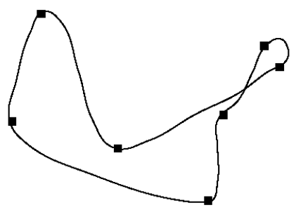
Figure 16
Note
In order to get kinks in the course of the curve despite the interpolation types Cubic, Akima and B-Spline, you have to evaluate the respective interpolation point twice. You do this by placing two vertices where you want the kink to appear.
- The Akima polygon type creates a smooth curve progression between the vertices, whereby the interpolated curve always goes exactly through the vertices. There is no overshoot (Figure 16). This type of interpolation sticks very closely to the specified curve, but can sometimes appear a bit too hard. In such a case, switch to cubic interpolation.
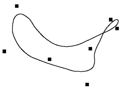
Figure 17
-
The B-Spline polygon type creates a smooth curve between the vertices, whereby the interpolated curve does not go through the vertices (Figure 17). The curve created in this way is extremely smooth. The support points only control the approximate course of the curve. Points that are further away have less influence on the course of the curve than points that are close by.
-
For temporal interpolation in animations, there is the special polygon type Spring (Figure 18), which is not actually an interpolation type. It causes an object, to which an animation path has been assigned, to move erratically from node to node. Positions between the bases are not reached.
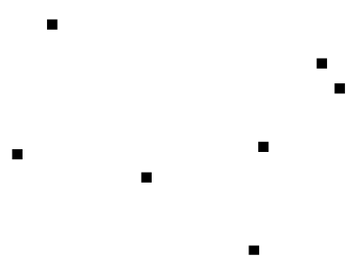
Figure 18
Each polygon can be closed (Figure 19) or open (Figure 20). If a polygon is closed, the start and end points are connected. There is a difference between closing a polygon and choosing the same start and end point. In the first case, the transition from the start to the end point is smooth, in the second case it is abrupt.
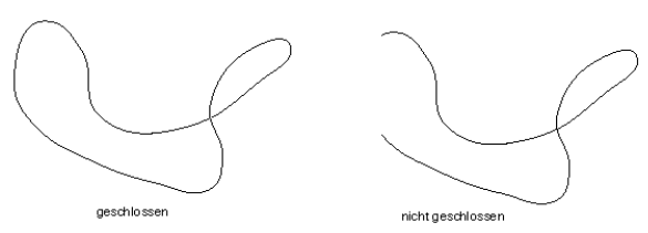
Figures 19 + 20
You can set the polygon type and closing of a polygon in the "Parameters" page of the "Information" window (Reference V.9.1).
For mathematicians:
Cubic interpolation is achieved by approximating the curve piecewise using cubic polynomials between vertices. For the polynomials, continuity in the first and second derivation at the support points is required in order to achieve the smoothest possible transition between the individual polynomials.
Akima interpolation is achieved by approximating the curve piecewise by cubic polynomials between vertices. In contrast to cubic interpolation, only continuity in the first derivation at the support points is required for the polynomials in order to achieve a smooth transition between the individual polynomials. Although this prevents the curve from overshooting, the curve does not always look as smooth due to the discontinuity in the curvature.
The B-spline interpolation is achieved by calculating a weighting function for each reference point, which reflects the influence of the point on the curve. In order to get a specific point on the interpolated curve, the coordinates of the support points are multiplied by the respective values of the weighting function, summed up and then give its position.
14. Light model
The fact that the human eye can perceive the surfaces of objects at all is because these surfaces reflect a certain proportion of the light falling on them and absorb the rest. In reality, however, it is unfortunately the case that this behavior depends in a complex way on the structure of the surface and the physical parameters of the material. In addition, there are often many light sources that illuminate a surface. In addition to direct sunlight, these are scattered light from the sky, as well as walls of houses or objects that produce indirect light. You can see this very well in a room with only one window through which sunlight enters. It is by no means the case that only the parts of space that are directly illuminated by sunlight are visible. Instead, all parts of the room are more or less diffusely illuminated.
A lifelike calculation and reproduction of all these factors is not feasible with the currently available algorithms and computers. Therefore, in practice, one is usually limited to a few parameters that approximate material and lighting. Which one you choose depends on the application of the three-dimensional graphics. For the interior design, for example, the radiosity method was devised, which very precisely calculates the indirect light that surfaces of other objects throw onto the surface to be calculated. Unfortunately, this method takes so much computing time that an implementation on the Amiga does not make sense. In addition, no reflections can be displayed with it.
A first approximation of MaxonCINEMA 4D is the decomposition of the entire visible wave spectrum into the three separate color areas red, green and blue. Similar to a color television, where all colors can be displayed by mixing the three primary colors red, green and blue, with MaxonCINEMA 4D the lighting is calculated separately for each of these color areas.
The indirect ambient light (e.g. indoors) is described by a constant value. A value of 0% red, 0% green and 30% blue would mean that the ambient light is dark blue. You could use it to simulate a scene at night. Of course, this is only a very rough approximation, but it is not that noticeable in practice, since the calculation of the direct light from a light source influences the appearance of a surface much more.
The color parameter exists for this. It indicates what percentage of the incident light is not absorbed by a material. A value of 100% red, 0% green and 0% blue means that the material appears red because all the green and blue components of the light are swallowed.
The same applies to the transparency parameter. It indicates what percentage of the incident light is allowed to pass through the surface. For example, if you want to create a material that only transmits green light, you must choose the values 0% red, 100% green, and 0% blue.
Unlike color and transparency, which describe how light coming from light sources is treated, specular reflects how much the material reflects light rays emanating from other objects. An ideal mirror has the values 100% red, 100% green and 100% blue.
Another important parameter for the appearance of the material is gloss. If you look at objects yourself, you will find that smooth surfaces such as glass or plastic in particular have a shiny white spot in some places, which is smaller the smoother the surface is. In MaxonCINEMA 4D you can determine the color and size of the highlight for a material. As a rule, the color white will correspond to the behavior of most surfaces. For metals such as bronze, brass or gold, you should choose a shade of yellow.
The Glossiness sets the size of the highlight. A value of 30% corresponds to a small highlight, such as that found on glass. A value of 50%, on the other hand, corresponds more closely to plastic, while a value of 80% results in a roughened surface. Of course, you can also switch off the gloss completely, for example if you want to create a rough wood surface that has no highlights at all.
Sometimes it is desirable for a surface to always have the same brightness — regardless of how brightly it is illuminated and from what angle it is viewed. The Luminescent parameter is responsible for this. If you set a luminous color, the surface will always appear in this color, even in complete darkness. In addition, the normal surface color is added when there is light.
To simulate water and glass, you can also specify the Refraction (refractive index) parameter. It indicates how much a ray of light is deflected by refraction when it passes through a surface - provided that this is transparent at all.
Note
If the description of the material parameters is too complicated for you, don't despair. You can access the extensive library of materials supplied at any time. The setting of individual parameters is actually only intended for professionals.
If the Fresrel option is switched off, the values entered for transparency and reflection are used regardless of the viewing angle. Otherwise, the angle is used to determine transparency and reflection. If you look at a pane of glass, for example, you will find that the pane of glass lets almost all light through and practically does not reflect when viewed perpendicularly. On the other hand, if you look at the glass pane (or e.g. a lake) from a shallow angle, then the entire environment is reflected in it without the objects underneath being visible. The distribution of transparency and reflection changes continuously between these two viewing positions. For example, if you entered the values 80% red, 80% green and 80% blue for transparency, the material is 80% transparent and 0% reflective when viewed perpendicularly, and 0% transparent and 80% reflective when viewed very flat. If you have also entered values greater than zero for mirroring, these are always added to the angle-dependent values.
The parameters of color, transparency and reflection depend in a complicated way on the angles that the light sources and the camera make to the surface. A surface that is irradiated with light perpendicularly naturally appears brighter than one that is only touched by the light at a flat angle. However, a precise explanation of these relationships would go beyond the scope of this manual. Reference is therefore made to the literature, in particular [1] (Appendix 3).
15. Colors
Colors determine the aesthetic and technical value of an image. Used sensibly, they not only increase the information content, but also the realism of the representation of natural objects, which sets the benchmark for programs such as MaxonCINEMA 4D.
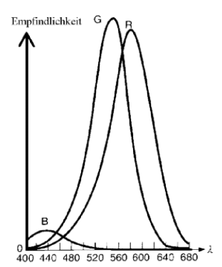
Figure 21
The human eye can distinguish several hundred thousand colors in the spectral range between 400nm (blue) and 700nm (red). The color perception of the human eye comes about through many thousands of receptors on the retina. However, the receptors are not all equally sensitive and certainly not in the same wavelength range (Figure 21). Some of the receptors are particularly sensitive in the blue wavelength range around 440nm. The remaining receptors are far more sensitive, with some being sensitive in the green range around 540 nm and the other in the range around 580 nm.
The eye therefore has three different types of receptors for the primary colors red, green and blue. However, their spectral sensitivity and overlapping of the sensitive areas make the characterization of colors a difficult problem.
The color that the human eye perceives as white therefore does not consist of equally strong portions of red, green and blue light, which is referred to as chromatic, but must be mixed together in different strengths according to the overlapping sensitivity ranges. Only then does the eye see white. In this case one also speaks of achromatic light.
Output devices for the representation of color can be a printer, film or computer monitor. The first two work according to the subtractive method of color mixing (CMY) and will not be discussed further here. Important for Maxon CINEMA 4D is the additive process of color mixing, which is carried out when colors are reproduced on the monitor.
In MaxonCINEMA 4D, colors are always characterized by specifying three values.
You have two different color models at your disposal, which you can switch between at any time.
The most well-known color model is the RGB model. Most graphics programs work with it because it is based on the technical conditions of the hardware for image or color output. The output device is usually the computer monitor. Its screen consists of a fine grid of dots, each made up of a red, green and blue dot. These points can be controlled by the electronics of the monitor with an electron beam. If not only a single color dot is controlled, but e.g. the red and the green dot at the same time, then the color values add up to yellow.
The colorants for the dots on the monitor are selected in such a way that, when added together in equal parts of intensity, they result in a white that comes closest to the human perception of a pure white hue.
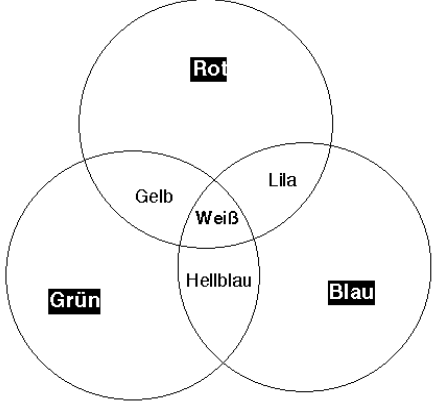
Figure 22
If different intensities are used for the three points, in addition to the 8 primary colors (black, red, green, yellow, blue, purple, light blue and white), which result from mixing the three primary colors according to Figure 22, any number of mixed colors can be used respectively. Their number is determined by the number of gradations with which the intensity of the electron beam is regulated.
Using 4 shades per primary color results in 4 red x 4 green x 4 blue = 64 hues. The standard is 256 gradations per primary color, so you can therefore create 256 red x 256 green x 256 blue = 16777216 color tones.
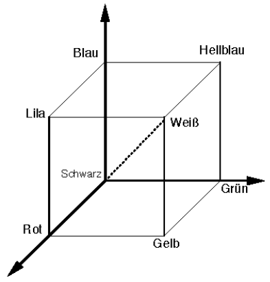
Figure 23
The colors can also be represented in a three-dimensional coordinate system (Figure 23). The coordinate axes are formed by the three primary colors. Black is at the origin. Mixed colors between red and green are formed in the ground plane. If you go a little higher, more and more blue is mixed in until you finally have white in the front corner of the cube. All shades of white lie on a connecting line between the origin and this corner.
The HSV model is more suitable than the technically oriented RGB model because it supports the human way of thinking and working, especially of painters and artists.
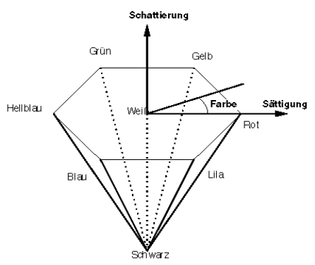
Figure 24
Note
In MaxonCINEMA4D, H, S are always specified as a percentage. An H value of 100% corresponds to 360°, while an S value of 50% corresponds to 0.5.
H (hue) stands for hue, S (saturation) for color saturation and V (value) for shading. Figure 24 makes it clear what is meant by this. The six primary colors red, yellow, green, light blue, blue and purple are arranged hexagonally around the color white. With the color black, a hexagonal structure results. The hue H now indicates the angle, starting at 0° for red, going through 180° for light blue and ending at 270° for purple. The saturation S is always measured radially outwards. Inside, on the Black! whiteaxis, it has the value 0.0. Outside, at the edge of the hexagon, the value 1.0. The greater the saturation, the more intense the hue. However, the hue will not change if you only change the saturation. Finally, the shade V is measured along the black-white axis. It has a value of 1.0 at the height of white and decreases continuously downwards until it reaches 0.0 for black. In a way, you can use shading to darken a hue.
So the following can be summarized:
- The pure color pigments can be found on the edge of the hexagon for V=1.0 and S=1.0.
- Fine white tint is added by reducing the saturation S.
- Fine black tint is added by lowering the shading V.
16. Materials and Textures
In MaxonCINEMA 4D you can assign a material to each object. For this purpose, the name of the assigned material is displayed in the "Information" window on the "Parameter" page. Click on the 'Materiaf' icon to select. Alternatively, you can also invoke the 'Select Material' function in the 'Edit' menu (Reference V.2.8).
Note
Newly created objects are automatically assigned the built-in white standard material by MaxonCINEMA4D.
Materials can also contain textures. These are images that are wrapped (projected) around objects in various ways. To assign a texture to a material, you simply have to enter the text name.
MaxonCINEMA 4D knows three different types of projection: surface projection, spherical projection and texture projection.
-
In plane projection, the texture image is projected onto an object orthogonal to its image plane (Figures 25 and 26).
-
The cylindrical projection is the intersection of area and spherical projection (Figures 27 and 28). It is often used for rotationally symmetrical objects (e.g. cylinders or screw objects). For example, you can use cylindrical projection to stick labels on cans.
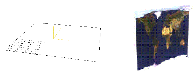
Figure 25 + 26
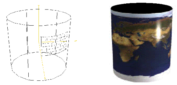
Figure 27 + 28
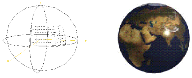
Figure 29 + 30
- The spherical projection puts the texture image spherically around an object (figure 29 and 30). It works just like you would fit a rectangular atlas map around a terrestrial globe.
Normally you can only put a texture once (1x) on the surface of an object. However, for many objects, for example the floor, it is desirable that the texture appears multiple times. You can achieve this by activating the "Rachel Texture" icon (Reference Ill.4.). Then the texture is projected onto the object so many times that it is completely covered with the texture (Figure 31). The texture connects seamlessly to itself.
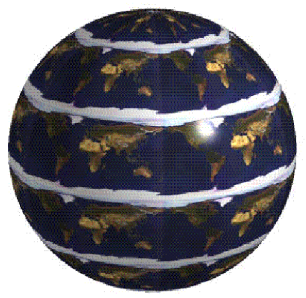
Figure 31
How the textures are wrapped is not determined by the material. You can set this with the texture bar, among other things.
To place the texture you need to activate the "Edit texture" icon. The texture of the active object is then displayed and can be moved and changed in real time.
The separation between texture data, which is always saved with the object, and the material data, which can be found in a separate material list, was chosen on purpose.
For example, imagine a scene with a sphere, a cube, and a cylinder. Each of these objects should have a different texture setting, e.g. a sphere texture for the sphere, a cylinder texture for the cylinder, and finally a face texture for the box. You can now assign the same material to each of the three objects without having to create three different materials.
17. Smoothing
"Smoothing" (Phong-Shading) is a function built into MaxonCINEMA 4D, with which you can achieve that an object made up of triangles and squares gets a rounder, smoother appearance during image calculation. For example, a sphere made up of a hundred triangles and which normally appears faceted (Figure 32) can hardly be distinguished from the perfect sphere with smoothing switched on (Figure 33). Differences in quality can only be seen at the edge of the sphere, because the silhouette of an object that is not mathematically perfect remains angular.
"Smoothing" is a suitable means of saving a lot of computing time and storage space. Because in the conventional way you would have to divide a round object into several thousand triangles before it really looks round. A condition for smoothing is that abutting surfaces have points in common.
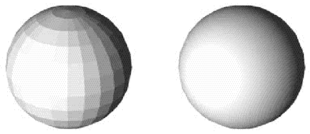
Figure 32 + 33
"Smooth" works according to the following principle: During image calculation, a normal vector is generated from the corner points of the area for each area that is to be illuminated. The brightness and color of a point are determined from the angles it forms with the rays of the camera and the light sources.
Normally, when two faces meet, there is a hard transition since each face has its own normal vector. There is then a jump in brightness at the edge.
If the "Smooth" option is activated, then the normal vector is interpolated. It gradually changes from the normal vector of one surface to that of the other surface. There is a smooth transition.
When calculating the image without "smoothing", it is irrelevant whether the normal vector starts on one side or the other of a surface. However, when interpolating, it is imperative that the normal vectors are properly aligned. In Figure 34 on the left you can see how two surfaces meet each other, the normal vectors of which are sometimes oriented up and sometimes down (although they are all perpendicular to the surfaces). The result is shown below. The interpolated vectors sometimes fold to one side and sometimes to the other. As a result, unsightly dark stripes and spots appear on the illuminated surface. This destroys the three-dimensional appearance of objects.
Figure 34
In Figure 34 on the right you can see how it should actually be. The normal vectors of the surfaces point uniformly to one side and therefore incline during interpolation as if the surface were actually curved and not angular. This results in a soft brightness gradient that increases the plasticity of objects.
What remains to be said is that when smoothing, you must ensure that all normal vectors of an object point uniformly outwards or to one side.
In principle, new objects are created with correctly oriented normal vectors and therefore do not have to be post-processed.
18. Image output
During the development of MaxonCINEMA 4D, particular attention was paid to the correct output of calculated images. An important concept here is the side ratio. It indicates the ratio of the visible width to the visible height of the monitor image. Normally it is always 4:3. If the aspect ratio is not taken into account, then circles on the screen are output as ellipses. Some monitors, for example, have stripes on the right and left edges, so the aspect ratio of 4:3 is no longer correct.
Note
To determine the aspect ratio for your monitor, you only need to measure the width and height of the visible monitor image. You then enter the two \values when selecting the corresponding screen mode.
Once this value is set correctly, there will be no more distortions in MaxonCINEMA 4D.
This concept was also retained for the perspective displays: if you reduce the image to be calculated by half in the Y-direction, you only see a smaller image section in the Y-direction, but it is completely undistorted. The calculated image was then practically recorded using widescreen technology. The output is always such that the full width of the image set in the editor is visible. The height, on the other hand, is adjusted to match the aspect ratio.
Attention: This can also have unexpected consequences. For example, it is often the case that an object is displayed completely in the Y-direction of the editor window, but a part of the object extends beyond the edge of the screen in the perspective displays. For longer calculation processes, therefore, always start a test image first or look at the scene in the wire diagram with the same screen mode and the same aspect ratio.
19. Working method
The following procedure is recommended for creating extensive scenes:
- First create the objects
- Group the objects in a hierarchy
- Place the objects in the correct places in 3D space
- Create the necessary materials
- Place any existing textures on the objects.
- Define the light sources required to illuminate the scene
- Check the scene by calculating test images
- Only then let the scene be calculated in the highest quality and resolution
- Animate the scene with the professional version of MaxonCINEMA 4D
Proceeding this way makes it easier to keep track of things and can save you a lot of time.
20. Animation
MaxonCINEMA 4D Professional allows the creation of extensive and highly complex animations. For this purpose, MaxonCINEMA 4D offers extensive aids and tools that allow almost every conceivable type of animation.
The important thing is that the concept of non-modal windows and asynchronous operation is retained even with animations. You have access to all functions at all times and can immediately see the effects of a parameter change. There is therefore no "animation mode".
The individual animation functions are explained in detail in the reference. The animation tutorial, which uses examples to explain the basic animation methods, is also helpful.
20.1 Keyframe Animation
With this type of animation, you can create animations very easily and conveniently by first specifying a specific point in time, then moving the objects to the appropriate position, and finally pressing the record button. At this point in time, MaxonCINEMA 4D saves the data for the position, size and location of the moving objects in a key. The name keyframe, or key for short, comes from English and means something like "keyframe" or "key scene".
A key is like a snapshot. It records the current spatial position (and other data) of an object.
After you have entered multiple keys, MaxonCINEMA 4D can interpolate between the keys. For a walking person, for example, it is sufficient to create a key each time the person has taken a step further. All positions in between are calculated by the program with any number of images.
Just two keys are enough to create a finished — albeit quite boring — animation. If you have three or more keys, you can use four other types of interpolation in addition to the linear type (Basics 13.).
20.2 Keys, Sequences, Tracks and Blocks
One or more keys together form a sequence, sequences are time ranges that contain a specific type of interpolation. In addition, they guarantee that no further object movement takes place outside of their time range. For example, a position sequence can go from time 5 seconds to time 8 seconds. All keys of this sequence fall between these limits in time. If you set B-spline interpolation for the sequence, then the keys will be interpolated using this method.
If you still don't understand the benefits of multiple sequences, please consider the Enterprise. It should accelerate from an out-of-frame position and fly into the camera's field of view. Suddenly, a Klingon starship appears and the Enterprise is forced to slow to a halt. After several seconds, however, it becomes clear that the Klingons are not hostile to the Enterprise and so the Enterprise happily flies on its way again...
For this hypothetical animation, you'll need two sequences: one leading up to the Enterprise stopping, and the second starting from the moment it accelerates again. Because if you only had one laid out in a sequence, it would have been impossible to keep the Enterprise standing still. All types of interpolation except linear and jump tend to overshoot or undershoot. In our specific case, this would have meant that the Enterprise would fidget uneasily.
With keyframe animation, you don't have to worry about sequences. The sequences are created automatically and without you noticing. If you have special cases were splitting into two or more sequences is necessary, then you can do it in the "Timeline" window (Reference V.7.).
The next higher unit above the sequences is the track. A track contains all sequences of a certain type, for example, all position sequences. There are tracks for the position, for the dimensions, for the location, for the material, for the texture, for special effects, etc. Each track gets its own line in the "Timeline" window, in which the sequences are then displayed with their keys will.
Finally, there are the blocks, which combine all tracks into one unit.
20.3 Path Animation
In many cases, it's easier to specify a specific spatial curve for an object's movement than to specify it through multiple keys. This is very easy to do in MaxonCINEMA 4D since any polygon can be used as the basis for a motion path.
For example, if you want a car to drive down a winding road, you can use the same polygon that you used to create the road to animate it. Just assign the polygon to the car as a space curve and the car will drive across the street.
There are additional functions that lead an object tangentially to the path so that the car also turns the body and turns the wheels in the courses. Otherwise, the car would slide parallel-shifted through the curves.
In addition, you can define realistic braking and acceleration manoeuvres so that the car brakes before a curve and then accelerates again afterwards.
20.4 Hierarchy Animation
Probably the most important aspect of generating realistic animations is the ability to also use and animate object hierarchies.
Every object can be animated in MaxonCINEMA 4D, e.g. through keyframe animation or through path animation. Normally, if the object has sub-objects, they just move with it as if they were attached to their parent.
You can also animate each sub-object individually. If the parent object is already moving, the child object's motion will be superimposed on it.
To do this, please imagine the object "Helicopter", which should consist of the sub-objects "Fuselage" and "Rotor". First, you can set the sub-object "Rotor" in motion. Next, you can assign a movement path to the entire "Helicopter" object, which lets the helicopter fly around a building, for example. During this flight, however, the rotor turns constantly without you having to adjust the movement of the rotor during flight.
With multi-layered animation—that is, even more, nested in the hierarchy—the motions performed can be even more complex, although you can still easily type them.
For example, think of a spacecraft that takes off, retracting its landing legs while pivoting away and performing a roll about its longitudinal axis. At the same time, another wheel screen rotates on the spaceship and the wings fold into a certain position. Each of the individual movements can be entered easily. Together, however, a highly complex movement process results.
Extremely important for understanding all hierarchy animation functions is the fact that MaxonCINEMA 4D remembers all animation data of an object with regard to the axis system of its parent objects. This usually happens unnoticed, since for many objects there is no superordinate object and therefore everything refers to world coordinates. Now think again about the helicopter from earlier. Suppose you have the helicopter crooked in the world coordinate system and now delete it without its sub-objects. At this very moment, the rotor (and all other parts on the same hierarchical level) “jump” to a new position. Because MaxonCINEMA 4D only noticed for the rotor object: "Turn around your Y-axis by such and such a number of degrees!" Until now, this was done in the higher-level system of the helicopter. The moment it no longer exists, the superordinate system is the world coordinate system. And that's why the rotor is now also screwing around the Y-axis of the world coordinates.
Relativity is a purely internal matter that you don't really notice unless you change the hierarchy. It is therefore advisable to first create the hierarchies and only then animate them. The reverse order means a considerable additional effort.
Only the relativity to the superordinate system allows for the construction of sophisticated animation sequences. This allows you to independently construct and conveniently assemble several animated objects. For example, you can construct a complete human and a train and animate them separately. After that, it is possible to put the person on the train without any problems. Without reentering the animation for the human, the human automatically rides on the train.
Hierarchical animation is an extremely powerful tool. Make extensive use of it!
20.5 Skeleton Animation
When applying hierarchy animation to a human figure, for example, it is important that the individual elements — usually arms and legs — cannot fall apart. The human body has muscles and bones that define the joints. MaxonCINEMA 4D uses the axes of the objects instead of bones. You can animate objects instantly if you take care of certain things when creating and grouping objects.
MaxonCINEMA 4D gives you the option of placing the axis of an object anywhere in space. The origin of the axis represents the joint point in the animation. So if you enter an arm, you only need to move the axis to the upper part of the arm, where you want the joint to be later. The child always contains the joint that connects to the parent. MaxonCINEMA 4D automatically determines the bones of the skeleton from the predefined hierarchy.
20.6 Inverse Kinematics
Normally, with keyframe animation, you determine the position of the objects in space by activating the object in question and moving it accordingly. All sub-objects attached to it are moved rigidly.
But if, for example, you want to move an arm of the aforementioned human figure, it can be quite tedious to work through all the hierarchies. First, the upper arm has to be rotated correctly. But then the position of the forearm is not correct. Therefore, you need to activate the forearm and get it in the right position as well. However, the position of the hand and its fingers is not yet correct. So you have to repeat the process of activation and positioning many times, which is very troublesome.
Instead, MaxonCINEMA 4D offers you the option of using the “drag” function (Reference 1.7.). With this function, you simply grab one of the sub-objects (e.g. the hand) and all higher-level objects such as the forearm and upper arm follow the movement of the hand automatically. The whole arm can, of course, only be moved within its limits. Once stretched out, it cannot grow any longer.
With it, you can bring a synthetic actor to life very quickly. Just grab his hand and move it to a glass or put your foot on a stair step. In any case, the movements in the calculated animation will appear very natural.
20.7 Camera animation
Even the most complex animation gains spatial depth and intensity when the movement of the individual objects is accompanied by a movement of the camera. In MaxonCINEMA 4D you can handle the camera like an object and assign keys or paths. This opens up numerous interesting possibilities.
Tracking shots through a scene (fly-through) or past objects (fly-by) are realized in a matter of seconds.
One of many possibilities is to aim the camera at another object. It then keeps the object constantly in view, even if the camera and object are constantly moving. This is particularly effective when the camera and object move in opposite directions.
For example, in an animation, the camera is moving down a street and sees a car coming towards it. The car is getting bigger and bigger. When the car finally passes the camera, the camera automatically pans around to view the car moving away.
20.8 Material Animation
This type of animation is extremely interesting for special effects. You can use it to perform material metamorphoses. For example, a marble vase can turn into a brass vase. The whole thing is particularly impressive when, in addition to the material metamorphosis, there is also an object metamorphosis.
The "fading out" of an object is also very effective. To do this, all you have to do is increase the transparency of the materials used by an object while reducing the other parameters such as colour, shine, etc. The object then becomes more and more transparent until it disappears completely.
You can animate almost any material parameter. In addition to colour and transparency, these are e.g. gloss level, reflection, luminous component, gloss colour, etc.
20.9 Texture Animation
MaxonCINEMA 4D knows two types of texture animation. The first of the two runs automatically as part of the material animation. If a material is assigned an image sequence of textures, this sequence of images is automatically played during the animation. You can use this to create a switched-on television, for example. Another application is, for example, an animation series of relief textures, which can be used to simulate the waves of a lake, for example.
The highest level of perfection is the use of this animation option in the production of feature films. Digitized moving images of real actors' faces can be easily combined with synthetic human bodies and animated with MaxonCINEMA 4D.
The second type of texture animation is texture axis interpolation and texture placement. You can use this to move a texture on a surface, for example.
20.10 light animation
Just like bodies, light sources can also be moved with keyframe, hierarchy or path animation. By using hierarchies it is e.g. possible to connect the light sources to an object in such a way that they move like headlights.
In addition, you can animate all other light source parameters such as colour, range, beam angle, etc.
20.11 sun animation
If you are an architect or landscape designer, you can put this feature to good use. It allows you to realistically reproduce sunlight and shadows throughout the day.
MaxonCINEMA 4D calculates the scene for you with correct illumination by a light source that corresponds to the natural sun in terms of colour and position. The sun moves across the firmament during the animation. You can follow the influence of light and shadow on the building.
The sun even changes colour to reddish as it nears the horizon. This is achieved by an algorithm that takes the correct atmospheric conditions into account.
20.12 Special Effects
A popular way to create effective animations is special effects, such as making an object explode. Such movements are too complicated to be entered by hand.
The various special effects are discussed in detail in the reference. The most prominent special effect is the morphing of objects (object metamorphosis).