43 KiB
- II. The object bar
II. The object bar
The object bar includes all object-creating functions, the MaxonCINEMA 4D system extensions and the Boolean operations.
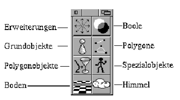
Figure 32
1. System Extensions
 If you click on this symbol and keep the mouse button pressed, a drop-down menu appears with all installed MaxonCINEMA 4D system extensions. System extensions are independent programs that can communicate with MaxonCINEMA 4D. They expand the functionality of MaxonCINEMA 4D without you having to wait for new program versions.
In order to install a system extension, you must place the corresponding program in the "Extensions" drawer, which is located in the MaxonCINEMA main directory. The next time you start the program, the system extension can then be accessed directly via the drop-down menu of the "system extensions" icon.
Even if you don't have a MaxonCINEMA 4D system extension, you can make extensive use of this function. You can place any objects constructed with MaxonCINEMA 4D in the "Extensions" drawer and then call them up in the program "at the touch of a button". If you need certain object shapes often, you can include them in the program this way!
2. Boolean
 MaxonCINEMA 4D offers you an interesting way of creating complex objects with Boolean operations. With these functions you can - similar to a workbench - cut holes out of objects, mill corners and glue parts.
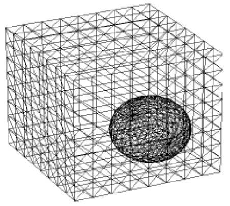
Figure 33
Note
The basic requirement for the Boolean operations are two massive, overlapping bodies. Unclosed bodies can lead to unforeseen results.
You should always use subdivided objects for Boolean operations (Figure 33).
The newly created object then produces significantly better results with the "Smooth" function than if the original objects were not subdivided (Figure 34).
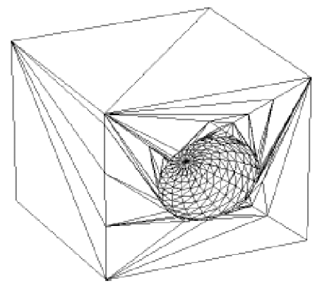
Figure 34
With objects created with Boolean operations, it can sometimes happen that, despite smoothing ('Phong shading') during image calculation, they have hard edges, as if smoothing were switched off. This is not an error in Boolean operations, but a fundamental problem: when objects with few subdivisions are intersected, very long, thin triangles are formed. These prevent the "smoothing" effect.
This can be remedied by subdividing objects. This automatically makes the newly created triangles smaller and more regular, which has a positive effect on the image calculation.
After calling a Boolean operation while holding down the Shift key, a window appears in which the two objects to be linked can be selected.
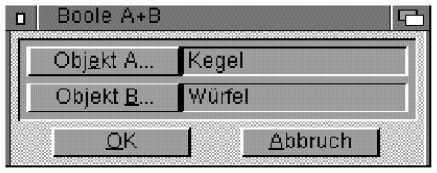
Figure 35
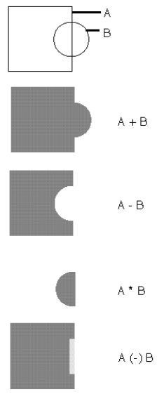
There are four different Boolean operations:
-
A + B
With this function you can merge the object (A) with another object (B) (Figure 36).
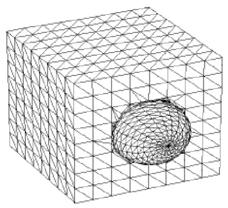
Figure 36: A + B
-
A - B
With this function you can subtract the object (B) from another object (A) (Figure 37).
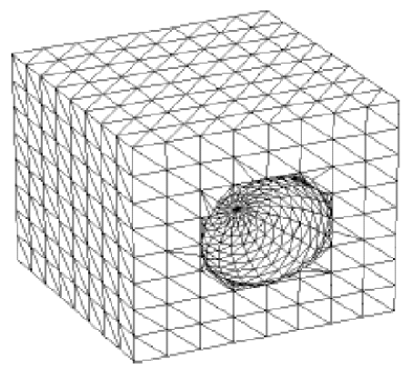
Figure 37: A - B
-
A * B
With this function, MaxonCINEMA 4D forms the intersection of an object (A) with the object (B) (Figure 38).
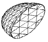
Figure 38: A * B
-
A - (B))
This function is similar to the A -B operation, but is actually not a true Boolean operation. It also cuts holes in the active object, but does not line the holes (Figure 39).
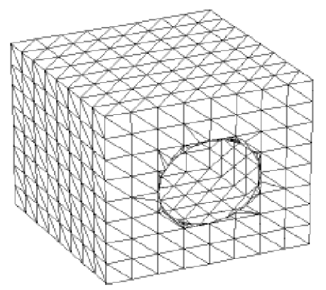
Figure 39: A - (B)
Note
With Boolean operations, the object hierarchy is fully retained. In addition, the original objects A and B are preserved. So if you only need the result produced by the Boolean operations, you have to delete the original objects. The figure below again shows all the functions in an overview.
Since Boolean operations are very computationally intensive, the "History" window, familiar from image calculation, appears.
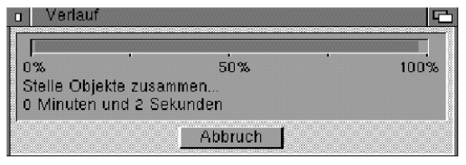
Figure 40
3. Basic Objects
 This icon hides a drop-down menu with thirteen basic objects from which you can very quickly assemble complex objects. You can change the parameters of the objects by selecting them with the right mouse button.
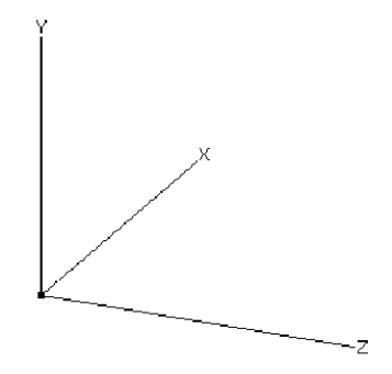
Figure 41
3.1 axis
You can use this function to create an "empty" object. It can only be recognized by its origin or its axes on the screen (Figure 41). You can later fill this object with points and areas, or simply use it to group other objects.
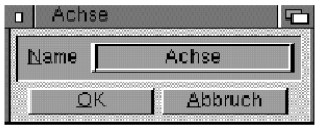
Figure 42
"Name"
Enter the name of the object here. It can consist of a maximum of 15 letters.
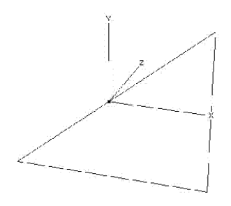
Figure 43
3.2 triangle
This function creates what is probably the most elementary object, the triangle (Figure 43). The triangle is always generated at right angles. The two legs are parallel to the X and Y axes of the world coordinate system.
Note
Please note that the triangle is not a solid. Difficulties can therefore arise in connection with Boolean operations and refractive materials.
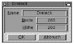
Figure 44
"Name"
Enter the name of the triangle here. It can consist of a maximum of 15 letters.
"Width", "Height"
Here you can set the width and height of the triangle. The triangle is created parallel to the XY plane of the world coordinate system.
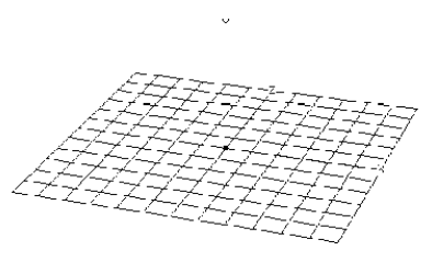
Figure 45
3.3 level
In contrast to the "Square" basic object, which only consists of a single area, the "Plane" function creates a quadrilateral that is subdivided into additional quadrilateral areas (Figure 45). The object is in the XZ plane of the world coordinate system.
The basic object “Layer” is very well suited for subsequent changes using the “Crinkle”, “Wrap” and “Deform” functions.
Note
Please note that the plane is not a solid. Difficulties can therefore arise in connection with Boolean operations and refractive materials.
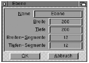
Figure 46
"Name"
Enter the name of the level here. It can be a maximum of 15 characters long.
"Width", "Depth"
Here you can expand the plane in X or Enter Z direction.
"Width Segments", "Depth Segments"
Here you can determine from how many squares the level is built. For example, if you enter 4 width segments and 3 depth segments, the object will be constructed from 3*4 squares.
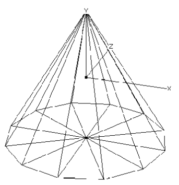
Figure 47
3.4 Cone
This function creates a cone whose bottom surface is in the XZ plane (Figure 47).
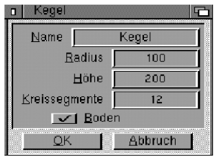
Figure 48
"Name"
Enter the name of the cone here. It can consist of a maximum of 15 letters.
"Radius"
Radius of the circular bottom surface of the cone in the XZ plane of the world coordinate system.
"Height"
Height of the cone from the disc to the apex.
"Circle segments"
Number of subdivisions. The cone shell and the bottom surface consist of the number of segments specified here.
"Floor"
With this option you can specify whether the cone has a bottom surface at all or whether it is open at the bottom.
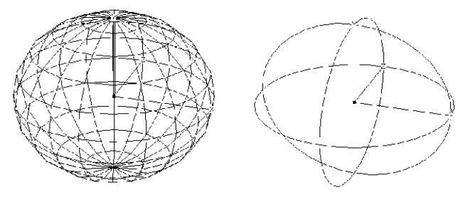
Figure 49 -50
3.5 bullet
This function creates a sphere consisting of either triangles and quadrilaterals (Figure 49) or a mathematically perfect sphere (Figure 50).
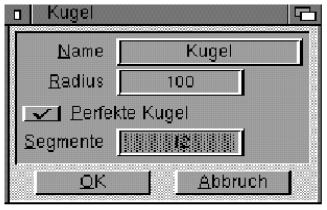
Figure 51
"Name"
Enter the name of the ball here. It can consist of a maximum of 15 letters.
"Radius"
Enter the radius of the sphere here.
"Perfect Sphere"
With this option you can specify whether you prefer a sphere made up of triangles and squares or a mathematically perfect sphere.
The perfect sphere has the advantage that it looks best when the image is calculated in the scanline algorithm and in the ray tracer, since it is the only one that is really round. In addition, it can be calculated very quickly - much faster than a sphere composed of surfaces. On the other hand, you cannot subsequently deform or alienate perfect spheres.
"Segments"
Here you can set how many segments the sphere should be divided into. The more segments you specify, the rounder the sphere looks. However, the memory requirements also increase and the display speed of the object is slowed down.
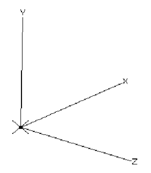
Figure 52
3.6 Light source
This function creates a standard shadow-casting light source that emits white light as a point without attenuation (Figure 52).
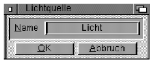
Figure 53
"Name"
Enter the name of the light source here. It can consist of a maximum of 15 letters.
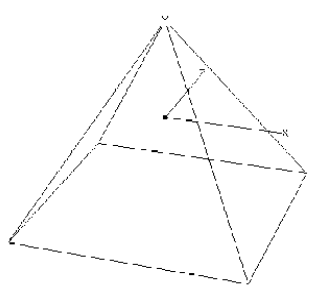
Figure 54
3.7 Pyramid
This function allows you to create a four-sided pyramid whose square base reads in the XZ plane of the world coordinate system and is oriented parallel to its axes (Figure 54).
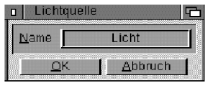
Figure 55
"Name" Leaves Enter the name of the pyramid here. It can consist of a maximum of 15 letters.
"Broad"
You can use this value to specify the edge length of the square base area.
"Height"
Enter here how far the top of the pyramid is in the Y-direction above the base.
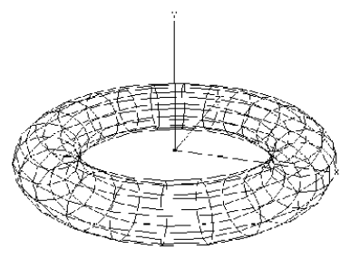
Figure 56
3.8 rings
This function creates a ring (torus) in the XZ plane (Figure 56).
Many ring and tube segments increase the memory requirement and reduce the display speed, but the object becomes rounder.
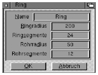
Figure 57
"Name"
Enter the name of the ring here. It can be a maximum of 15 characters long.
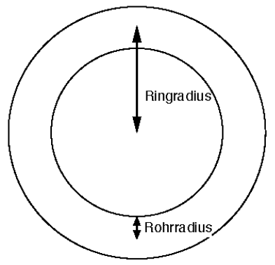
Figure 58
"Ring radius"
Here you enter the radius that determines the size of the ring (Figure 38).
"Ring segments"
Here you can specify how many segments the ring should consist of.
"Pipe radius"
The thickness of the tube, which winds on a circle with the ring radius, results from the tube radius.
"Pipe Segments"
This number indicates the subdivisions that a single segment of the ring should have.
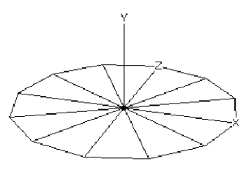
Figure 59
3.9 disc
This function creates a circular disk in the XZ plane (Figure 59).
Note
The disc is not a solid. Difficulties can therefore arise in connection with Boolean operations and refractive materials.
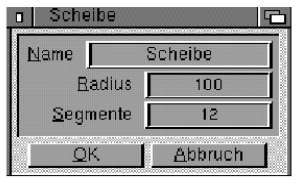
Figure 60
"Name"
Enter the name of the target here. It can consist of a maximum of 15 letters.
"Radius"
Enter the radius of the disk here.
"Segments"
Here you can specify how many segments the disc should be made up of.
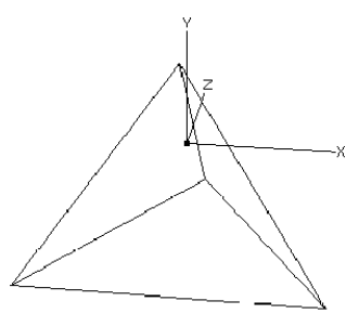
Figure 61
3.10 Tetrahedron
This function creates a three-sided pyramid (Figure 61). All four faces are equilateral triangles and have the same edge length. One of the side faces lies in the XZ plane of the world coordinate system, with one edge of the triangle being oriented parallel to the X axis.
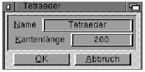
Figure 62
"Name"
Enter the name of the tetrahedron here. It can consist of a maximum of 15 letters.
"Edge length"
Here you can specify the edge length of the tetrahedron. If you want to know how far the vertex of the tetrahedron is above the XZ plane, you can calculate it using the following formula, where "k" is the edge length and "h'" is the height of the tetrahedron:
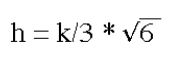
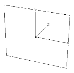
Figure 63
3.11 quadrilateral
This function creates a square in the XY plane (Figure 63). The sides of the quadrilateral are formed parallel to the X and Y axes of the world coordinate system.
Note
The quadrilateral is not a solid. Difficulties can therefore arise in connection with Boolean operations and refractive materials.
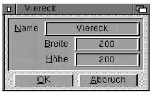
Figure 64
"Name"
Enter the name of the square here. It can consist of a maximum of 15 letters.
"Broad"
Here you can specify the width of the square in the X direction of the world coordinate system.
"Height"
Here you can set the height of the square in the Y direction of the world coordinate system.
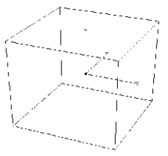
Figure 65
3.12 Cube
This function creates a cube. The pages are aligned parallel to the coordinate planes of the world coordinate system (Figure 65).
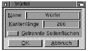
Figure 66
"Name"
Enter the name of the cube here. It can consist of a maximum of 15 letters.
"Edge length"
Here you can specify the edge length of the cube.
"Separate Faces"
For some applications it is convenient if the faces of the cube are single objects. You can, for example, put a different texture on each side face.
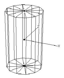
Figure 67
3.13 Cylinders
This function creates a cylinder from a number of triangles and squares (Figure 67). The cylinder axis is parallel to the Y-axis of the world coordinate system.
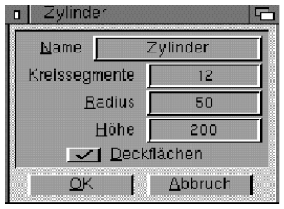
Figure 68
"Name"
Enter the name of the cylinder here. It can consist of a maximum of 15 letters.
"Circle segments"
Here you can specify from how many segments the bottom and top surface of the cylinder or the cylinder jacket should be made up. The cylinder jacket is made up of squares, the top surfaces are made up of triangles.
"Radius"
Enter the radius of the cylinder here.
"Height"
Here you can set the height of the cylinder.
"Cover surfaces"
Here you can specify whether you want a closed or an open cylinder.
4. Polygons
 With this icon you can call up various ready-made polygons that can be used immediately for object creation or animation.
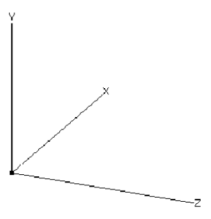
Figure 69
4.1 axis
With this function you can create an "empty" polygon object. It can only be recognized by its origin or its axes on the screen (Figure 69). You can later fill this object with points and areas, or simply use it to group other objects.
"Name"
Enter the name of the object here. It can consist of a maximum of 15 letters.
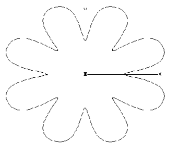
Figure 70
4.2 Flower
This function creates the contour of a flower with a selectable number of petals in the XY plane of the world coordinate system (Figure 70).
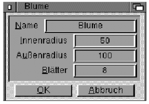
Figure 71
"Name"
Enter the name of the polygon here. It can consist of a maximum of 15 letters.
"Inner radius"
This value indicates the size of the interior area where the leaves attach.
"Outer radius"
The petals range from the inner radius to the outer radius.
"Petals"
Enter here how many petals should be created.
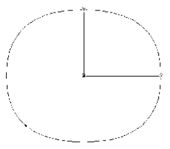
Figure 72
4.3 Circle
This function creates a circular polygon in the XY plane of the world coordinate system (Figure 72). It is very suitable for creating hoses or tubes with the "path object" function.
Note
Since the circular polygon is made up of only four support points and is interpolated using B-spline interpolation, the contour is not exactly circular. If the "circle" polygon is not round enough for you, you can use an "N-corner" with several (e.g. 24) corners instead.
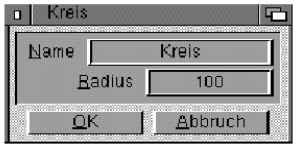
Figure 73
"Name"
Enter the name of the polygon here. It can consist of a maximum of 15 letters.
"Radius"
Select the radius of the circle here.
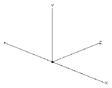
Figure 73b
4.4 line
This function creates a line parallel to the X-axis of the world coordinate system (Figure 73b).
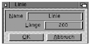
Figure 74
"Name"
Enter the name of the polygon here. It can consist of a maximum of 15 letters.
"Length"
Specify the length of the line here.
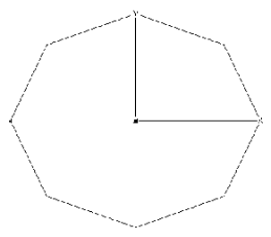
Figure 75
4.5 N corner
This function creates an angular, closed polygon in the XY plane of the world coordinate system (Figure 75). It is very suitable for creating hoses or tubes with the "path object" function.
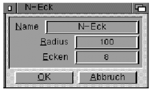
Figure 76
"Name"
Enter the name of the polygon here. It can consist of a maximum of 15 letters.
"Radius"
Here you select the radius on which the corners of the polygon are to lie.
"Corners"
Specifies the number of polygon corners.
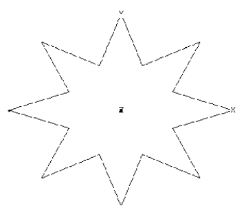
Figure 77
4.6 star
This function creates a closed, star-shaped polygon in the XY plane of the world coordinate system (Figure 77). It is very well suited, for example, for creating gears with the "move object" function.
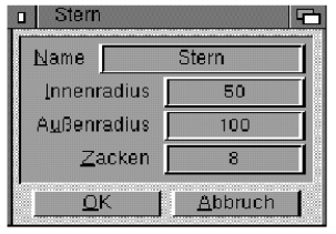
Figure 78
"Name"
Enter the name of the polygon here. It can consist of a maximum of 15 letters.
"Inner radius"
This value determines the size of the interior area where the spikes attach.
"Outer radius"
The spikes extend from the inner radius to the outer radius.
"Spikes"
Enter here how many spikes are to be generated.
5. Polygon Objects
Here you will find the most sophisticated functions for creating objects. You can wind a polygon around another polygon, e.g. to get a hose, or combine several closed polygons (layers) into one object, whereby these are automatically connected by triangles and squares. Half a dozen cross-sections of a human head, for example from a computer tomograph, result in a realistic "head" object in no time at all. With the simple outline of a letter, three-dimensional letters with rounded edges can be created very quickly. Another unique feature is the ability to specify holes in the forms.
All polygon feature functions require you to specify one or more contours. Common to all polygon objects is therefore the "Select contour" field, which opens a selection window for contours.
Each polygon object also offers the possibility of creating cover surfaces. You set the parameters by clicking on the "Cover surfaces" field.
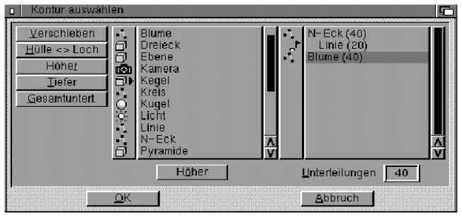
Figure 79
Select Contour window
A window with two lists appears. All available polygons are shown in the list on the left. If you select one of these polygons and click "Move", the name of the polygon will appear in the list on the right. The right list indicates which polygons have been selected. Instead of "Move" you can also double-click on the name of the polygon in the list on the left - unless the polygon has other sub-objects. In this case, the content of the polygon is displayed in the list on the left.

If you want to specify a hole polygon for a contour (e.g. for the letter "B", the contour must be supplemented by two hole polygons), then you must first bring it to the right side. Then mark it in the selection list on the right and use "Higher" or "Lower" to bring it to the position immediately below the contour. Then click Shell <> Hole. The name of the polygon in the right list is indented and marked with the 'hole' icon to distinguish it from the envelope polygons.
You can add more hole polygons in this way.
Unwanted polygons in the list on the right can be removed from the list with "Move".
Note
Note that the algorithm for calculating the end faces is very complex and takes a long time when using multiple hole polygons.
With "Subdivisions" you can specify for each contour how often it should be subdivided. A value of 20 is always entered by default. For polygons that are interpolated (Cubic, Akima, B-Spline), it is sometimes worth specifying a larger number of subdivisions (e.g. 40) so that the polygon object gets a round shape. You can also enter the value O. It means that no interpolated points, but the support points are taken directly.
If you click on "Total subdivisions", you can set the number of subdivisions for all contours at once.
"Ceiling" window
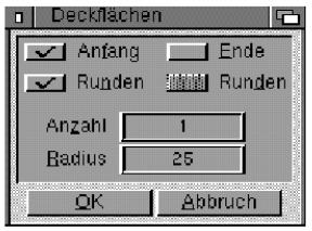
Figure 80
Here you can selectively specify with "Start" and "End" whether the start or end contour should be closed. Maxon CINEMA 4D automatically takes into account any existing hole polygons and assembles the cover surfaces accordingly.
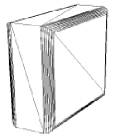
Figure 81
An interesting ability of MaxonCINEMA 4D is that the cover surfaces are not only placed flat on the start and end contours, but also that the edges are rounded (Figure 81). If you have activated the "Round" option, MaxonCINEMA 4D moves the edges of the cover surfaces in a selectable "Number" of steps so that the edges in the cross section form a quadrant with a selectable "Radius". Nothing stands in the way of creating professional 3D fonts.
Note, however, that the algorithm cannot perform miracles. Since the edges are always moved parallel to the starting edge, it can happen that the edges end up outside the object if you enter a radius that is too large. As the user, you must ensure that the radius values are within reasonable limits. Otherwise, MaxonCINEMA 4D cannot create the cover surfaces.
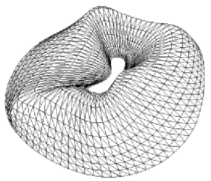
Figure 82
5.1 Morph Object
This extremely powerful feature allows you to create organic shapes relatively quickly and easily (Figure 82). You can specify several contours for this. MaxonCINEMA 4D connects the contours one after the other with a freely selectable number of points. You can also specify whether the connection between two contours should be direct or via a selectable type of interpolation. For example, you can construct a square bottle that ends in a round bottle neck that slopes downwards.
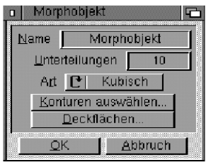
Figure 83
"Name"
Enter the name of the morph object here. It can consist of a maximum of 15 letters.
"Separations"
Select here the number of steps in which the transition between the first and last contour should take place.
"Type"
Here you can specify on which space curve the interpolated intermediate contours are to be located. Just like with polygons, you can choose between 'Linear', 'Akima', 'B-Spline' and 'Cubic'. With linear interpolation, the intermediate contours move directly between the specified contours, otherwise the movement is smoother and dependent on the subsequent contours.
"Select Contours", "Caps"
Use this to select the contours and set the parameters for the caps. You must specify at least three contours. If you accidentally chose the wrong order for the contours, you can correct this later with the "Higher" or "Lower" fields.
All contours must have the same number of divisions. If you have changed a value, MaxonCINEMA 4D automatically enters this in all other contours.
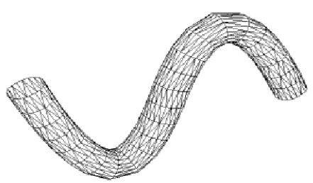
Figure 84
5.2 path object
This function allows you to place an outline along a path to create an object (Figure 84).
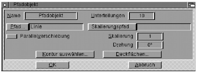
Figure 85
"Name"
Enter the name of the path object here. It can consist of a maximum of 15 letters.
"Separations"
Select here in how many steps the movement along the path should take place. The more subdivisions you choose, the smoother the path object will appear.
"Path"
Use this to select the polygon along which to move the contour.
"Parallel Shift'"
If you don't want the contour to follow the curves of the path but stay parallel to its original location, then enable this option. The contour is then not aligned to the start of the path the first time, but retains its position.
"Scaling"
You can linearly shrink or grow the contour as it moves along the path. For example, a scaling factor of 3.0 will increase the contour to three times its size, while a factor of 0.5 will halves the size.
The scaling is always linear. If you want non-linear scaling, you must use the "Scale Path".
Note
You don't need to use a scaling polygon for simple linear scaling. It is sufficient if you enter the desired value under "Scaling".
"Rotation"
You can additionally rotate the contour as you move along the path. The rotation is always about the Z axis (“show” axis) of the polygon.
"Scaling Path"
In order to have the size of the contour change along the path in a specified way, you can specify an additional "scale path". When creating the path object, MaxonCINEMA 4D then always calculates the current distance between the path polygon and the scaling polygon. If the distance is greater than the distance at the beginning of both polygons, the contour will increase, otherwise the contour will shrink (Figure 85b).
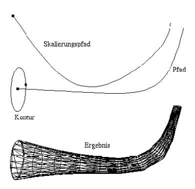
Figure 85b
As soon as you specify a scaling polygon, the linear scaling input field is locked. To be able to enter a numeric value again, you must click on "Scaling path" and select no object in the object selection window. You can do this by clicking in the free area below the selection list before exiting the window with "OK".
The MaxonCINEMA 4D layout algorithm is relatively difficult to understand. If you don't want to know exactly how the program works, you can skip this section.
MaxonCINEMA 4D first aligns the contour to the start of the path:
-
The contour's Z (“pointing”) axis is rotated so that it is tangent to the path.
-
The X-axis of the contour is rotated so that it lies in a plane parallel to the XY-plane of the path object coordinate system.
For example, if you place a contour along the pre-made "circle" polygon, then the X-axis of the contour lies in the plane defined by the circle.
-
The Y axis of the contour is placed so that it points in the opposite direction to the Z axis of the path.
For example, if you create a letter with an unsymmetrical outline, you must rotate the outline axes by 180° so that the outline “flips” inside out.
All of the following arrangements are based on the previous contour. The contour is rotated further so that its Z-axis is again tangential to the path. This rotation is clearly defined.
This algorithm achieves good and predictable results even with the most complex three-dimensional path polygons.
"Select Contour", "Caps"
Reference 1.5.1
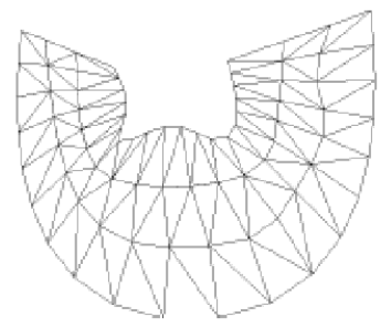
Figure 86
5.3 Layer Object
The layer object occupies a special position among the polygon objects, since here you can enter and control the appearance of an object layer by layer (Figure 86). For example, if you have entered several polygons (e.g. using images from a computer tomograph), you can connect them to get the three-dimensional head shell again.
Note
MaxonCINEMA 4D always begins connecting two contours at the beginning. Therefore, make sure that the beginning of the polygons are approximately together, otherwise the layered object will look twisted.
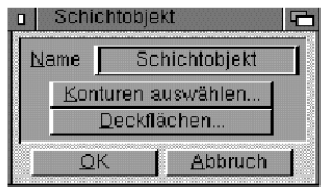
Figure 87
"Name"
Enter the name of the layer object here. It can consist of a maximum of 15 letters.
"Select Contours", "Caps"
Reference II.5.1
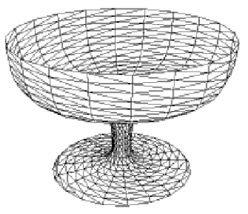
Figure 88
5.4 screw object
The screw object is very similar to the move object. Instead of moving a contour, you can rotate the contour around its Y axis (Figure 88). If you specify a displacement at the same time, the contour winds on a screw around the axis of rotation (Figure 90). In this way you can easily make threads and screws.
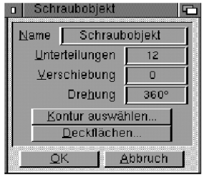
Figure 89
"Name"
Enter the name of the screw object here. It can consist of a maximum of 15 letters.
"Separations"
Select here in how many steps the rotation should take place. The more subdivisions you choose, the rounder the screw object will appear. For a 360° rotation, there should be 8 or more subdivisions.
"Shift"
Here you can specify how far the contour should move in the direction of the axis of rotation (Y-axis of the contour) during rotation. If you enter a displacement of 0, the contour only moves on a circle, otherwise on a screw.
"Rotation"
Enter the angle by which the contour should be rotated around the axis of rotation. For example, an angle of 720° corresponds to a double rotation.
"Select Contour", "Caps"
Reference 11.5.1
The arrangement of the contour along the screw path follows the rules described in the "path object" function (Reference 11.5.2).
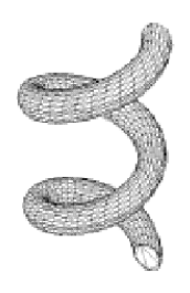
Figure 90
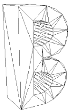
Figure 91
5.5 Move object
With this function you can move a polygon in a definable direction (Figure 91). MaxonCINEMA 4D automatically connects the original polygon and the moved polygon with quadrilaterals. If desired, the cover surfaces are closed so that the object is closed.
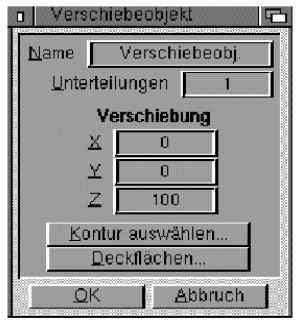
Figure 92
"Name"
Enter the name of the moving object here. It can consist of a maximum of 15 letters.
"Separations"
Select here the number of steps in which the shift should take place. A subdivision of 1 means that the initial and final contours are connected directly. If you intend to deform the object later, you can specify a higher number of subdivisions here. MaxonCINEMA 4D then inserts additional contours between the start and end contours.
"Shift"
Here you can specify the direction in which the contour should be moved. For example, if you have created the outline of a letter in the XY plane of the world coordinate system, you can extrude this outline with the offset (0, 0, 100) in depth.
"Select Contour", "Caps"
Reference 11.5.1.
6. Special Objects
 This symbol hides a collection of highly complex objects that can be created at the push of a button.
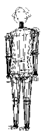
Figure 93
6.1 Figure
You can use this function to get an "animation-ready" character (Figure 93). Since all hierarchies have already been created, you can use the "drag" function to bring the figure into the desired position very easily.
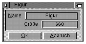
Figure 94
"Name"
Enter the character's name here. It can consist of a maximum of 15 letters.
"Size"
With "Size" you specify the Y extent of the figure. The other extents are adjusted proportionally.
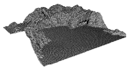
Figure 95
6.2 Fractal
The creation of wildly rugged mountains or rolling hills does this on demand. A mouse click is enough for a mountain range to appear on the screen.
The 'Fractal' function creates an irregularly shaped object based on the fractal principle (Figure 95).
First a simple quadrilateral is created in the XZ plane of the world coordinate system. MaxonCINEMA 4D then subdivides this quad into four smaller quads and randomly shifts the points where the large quad was subdivided by a value 'w' up or down along the Y-axis.
Then each of the four small squares is subdivided into four even smaller squares, making a total of 16 squares. Again, their partial points are randomly shifted up or down, but this time only by a maximum of half of "w". This is repeated until the desired subdivision level is reached. As a result, complex mountains with many details are formed from a rough structure with a few squares.
l but the squares generated are no longer flat, MaxonCINEMÄA 4D divides them into two triangles at the end.
If MaxonCINEMA 4D didn't halve the maximum value for the random displacement after each subdivision step, you would only get an entity resembling a steel brush or a hedgehog instead of a mountain. Namely, the basic principle of fractal structures is to add small randomnesses to data depending on that data. Without this dependency, all you get is a tangled set of data.
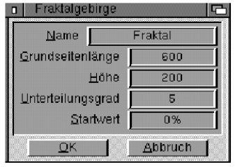
Figure 96
"Name"
Enter the name of the fractal here. It can consist of a maximum of 15 letters.
"base length"
Here you can enter the edge length for the fractal, which has a square base in the XZ plane.
"Height"
This value determines the height of the fractal. The fractal is formed in such a way that the mountains unfold in the direction of the positive Y-axis. Values below the XZ plane (the floor) are clipped.
"degree of subdivision"
This numerical value allows you to specify how often the subdivision operation should be performed. Starting from a single quadrilateral with a degree of subdivision of n, you get a number of 2" quadrilaterals. Since all quadrilaterals are subdivided into triangles at the end, you even get twice as many triangles.
Don't specify too high degrees of subdivision, since each higher degree requires four times as much storage space.
"seed value"
If a completely random function were used to randomly shift the partial points, you would get a different mountain range each time you called the "Fractal" function.
For this reason, MaxonCINEMA 4D uses a quasi-random function that can be started with a numerical value. If the values are the same, you get the same mountain range every time. You can freely choose the numerical value between 0% and 100%.
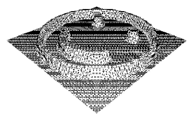
Figure 97
6.3 Elevation Relief
This function interprets the gray values of an image as height values and converts them into a three-dimensional relief. The relief is created in the XZ plane of the world coordinate system (Figure 97).
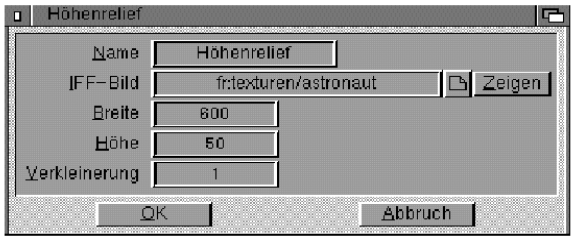
Figure 98
The average of the red, green and blue values of an image pixel is interpreted as the height. Black corresponds to the minimum height, while white corresponds to the maximum height.
"Name"
Enter the name of the relief here. It can consist of a maximum of 15 letters.
"LFF Image"
Here you enter the path name for the image from which the relief is to be created. To check whether you are using the correct image or whether the path name is correct, you can test the image by clicking on the "Show" field. MaxonCINEMA 4D now loads the image into memory and displays it on the screen. The display is ended with a mouse click. The width, height and color depth of the image are then displayed in a window.
"Broad"
Here you can enter the edge length of the elevation relief, which has a rectangular ground plan in the XZ plane. While the width is set using "Width", the depth of the relief results from the combination of "Width" and the format of the image. For example, if you specified a width of 600 units, but the image is 300x200 pixels, the height relief will be 400 units deep.
Note
Do not use values for the height that are too high, otherwise the image can no longer be perceived due to the exaggerated relief effect.
"Height"
This value determines the height of the relief. The relief is formed so that it unfolds in the Y-axis direction.
"Reduction"
This factor indicates whether every color pixel of an image should really be converted. Two triangles are generated per pixel. With a "small" image with a resolution of only 320x256 pixels, that is 163840 triangles, which MaxonCINEMA 4D does not allow. Objects can only contain a maximum of 65520 triangles. If MaxonCINEMA 4D notices that the permissible limit has been exceeded, the program automatically reduces the image to a lower resolution. This happens automatically and without your intervention. Here you can only explicitly enter whether such a reduction should always take place, i.e. without exceeding the limit.
For example, if you change the reduction value to 3, 3x3 pixels of the image are always added together to form a single height value. The higher the Reduction value, the smaller the number of triangles generated. At the same time, however, more and more high-level details are lost.
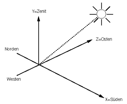
Figure 99
6.4 Sun
This function, which generates a light source that simulates the sun, is particularly interesting for architects. All you have to do is enter the date and your scene will be illuminated with a light source that reflects the correct direction and even the correct color of the sun. To do this, the date, time (CET) and geographic latitude must be entered.
Note
The sun is always created as a light source with the name "sun".
The X-axis of the world coordinate system is assumed to be the southern direction, where the sun is always at 12 noon. East (sunrise) is therefore in the direction of the z-axis, west is in the direction of the negative z-axis, and north is in the direction of the negative x-axis (Figure 99). Since MaxonCINEMA 4D cannot create infinitely distant light sources, the light source is simply placed at a very large distance from the origin of the world coordinate system. In addition, the light source emits parallel light.
The sun is generated only when it is above the horizon (day).
The color of the sun is not pure white, but corresponds to the yellowish light changed by the absorption spectrum of the atmosphere, which shifts into the red spectral range as the sun approaches the horizon.
The "Sun" function is intended for users who want to simulate realistic colors and shadows at different times of the day, for example when planning a landscape or building a house.
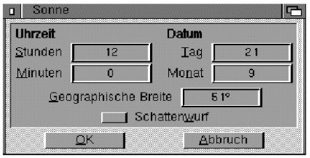
Figure 100
"Time date"
Enter the time (CET) and the date for which the position of the sun is to be calculated. Daylight saving time is not taken into account, so you have to subtract one hour from daylight saving time (CEST) for the summer months to get Central European Time (CET).
"Latitude"
Enter the latitude of your location on the earth's surface here. For Munich this is about 48°, for Frankfurt 50.1° and for Hamburg 53.6°.
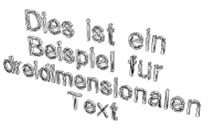
Figure 101
6.5 Text
This function is particularly interesting for titling videos, as it makes it very easy to create three-dimensional lettering. All you have to do is type in some text or load an ASCII file and you will have an object consisting of three-dimensional letters (Figure 101).
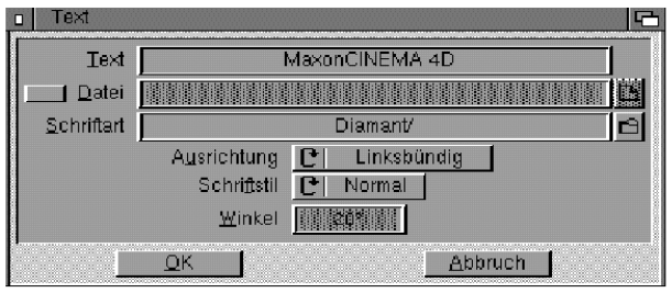
Figure 102
"Text", "File"
Here you type in the text you want MaxonCINEMA 4D to generate. If you want to use an ASCII file for text generation, activate the "File" option and enter the file name.
"Font"
Here you can specify which font you want to use. Two fonts are already included in the scope of delivery of MaxonCINEMA 4D. You can use a variety of free public domain fonts or create your own fonts (see below). Numerous polygons are supplied for creating your own fonts, which you can use as a starting point for creating three-dimensional letters.
"alignment"
If you use a multi-line ASCII file as text, you can specify how the three-dimensional text should be formatted. You can align the text left, right, or centered.
"font style"
Here you can set the attributes "Normal" and "Italic".
"Angle"
If you have selected an italic font style, MaxonCINEMA 4D will slant the letters at the angle specified here. The larger the angle, the more italic the letters are.
If you want to create your own character set, you must proceed according to the following rules:
-
When creating the letters, make sure that they are oriented parallel to the world coordinate axes. For example, the letter "H" should be placed so that the horizontal bar is parallel to the x-axis and the two vertical bars are parallel to the y-axis of the world coordinate system. Position the letters so that their baseline is on the x-axis of the world coordinate system.
-
Create a drawer for the font under its name on disk.
-
You then save the three-dimensional letters individually in this drawer. Name the letters with their corresponding ASCII numbers. For example, save the letter "a" under the name "87" and the letter "A" under the name "65".
-
MaxonCINEMA 4D always places the letters consecutively. Because they are different sizes—the “i” object is narrower than the “W” object—proportional fonts are usually always created unless you make sure that all letters have the same dimensions in the X direction when you create them .
-
MaxonCINEMA 4D must be informed of the distance between letters and the distance between the lines. You must therefore also store an ASCII file with the name "Description" in the drawer of the character set, in which character and line spacing are specified. You also need to specify how wide a space is.
Character spacing is the space between two characters, while line spacing is the distance between the baselines of two lines.
The file must have the following structure:
  Character Spacing <value>
  Line spacing <value>
  space <value>
It is best to copy one of the supplied descriptions and only change the respective values.
It is of course up to you what you store under a specific ASCII number for an object. For example, you could define a character set of chess pieces.
3.7 Ground
 The floor is a special object because it can only exist once. Regardless of its object axes, it always lies in the XZ plane and goes through the origin of the world coordinate system. However, you can freely assign materials and textures to it.
Note
It is advisable to always use tile textures for the floor, since a texture should usually cover the entire floor up to the horizon.
You can toggle the floor on or off by selecting this icon. When the ground is turned on, it will have a check mark in the menu. In addition, when the point bar is open, the "ground" symbol is depressed.
The ground is only displayed during the image calculation. It is only visible on the desktop if it has been activated as an object.
3.8 Sky
 The sky is an infinite sphere centered at the origin of the world coordinate system. The sky is a similar special object as the ground. There can only be one sky in the scene.
You can turn the sky on or off by selecting this icon.
The sky is only displayed during image calculation. It is only visible on the desktop if it has been activated as an object.
To edit the sky texture, a solid spherical surface appears as a boundary on which you can freely move the texture. This spherical surface represents the actually infinite celestial sphere, which, however, cannot be represented in this way. They therefore have to deal with a finitely large sphere. So don't be confused by the fact that other objects appear to be outside of this spherical surface shown.