65 KiB
- I. The main bar
I. The main bar
The main bar contains the most important and most frequently used symbols and functions of MaxonCINEMA 4D. It is divided into five areas:
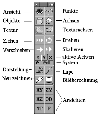
Figure 1
The top six icons (Edit View, Edit Points, Edit Object, Edit Axes, Edit Texture, Edit Texture Axes) indicate what type of object or part of an object is currently editable. For example, if you have activated the "Edit object" icon, you can move, scale and rotate objects. On the other hand, if you clicked on the "Edit points" icon, you can edit the points of the object.
Only one of the six icons is activated (depressed) at any time. As soon as you select a different icon, the old one will be disabled.
The next four icons (Move, Scale, Rotate, and Drag) are action icons. They specify what action the mouse input should be translated into. For example, a right-left movement of the mouse can be used to enlarge or rotate an object.
Here, too, you can only carry out one action at a time. If you click another action, the old action will be deactivated.
The next group of four items ("X", "Y", "Z" and "Axis System" icons) determine how the action you set with the action icons will be performed. For example, by deactivating the "X" symbol, you can lock the X axis, i.e. an object can then only be moved in the Y and Z direction and no longer in the X direction.
The next four icons ('View', 'Magnifying Glass', 'Redraw' and 'Calculate') are themed collections of commonly used functions. For example, you can use the magnifying glass to enlarge the visible section of the workspace.
Finally, there is a group of six icons ("XY", "ZY", "XZ", "3D", "4T", and "P") that are used to select the view in the active document window.
1. Edit view
 Activating this icon allows you to edit the view of the active document window. All actions now affect the view. With the two-dimensional views (XY, ZY, XZ) you can move and enlarge the displayed section, with the three-dimensional views (3D, P, and 4T) you can change the editor or "perspective" camera.
You can navigate the room with the mouse in the following ways:
When moving, the camera always moves in the opposite direction to the mouse input, i.e. if you move to the left, the camera is moved to the right, which means that the objects to be displayed move to the left. This is the most intuitive and easiest to learn method. Since the mouse only allows two-dimensional input, MaxonCINEMA 4D uses the right mouse button. If you keep it pressed, you can control the back-and-forth movement in addition to the right-left or up-down movement (a right-left movement while the right mouse button is pressed is interpreted as a back-and-forth movement). You can switch between the left and right mouse button at any time during the moving process.
You can cancel the moving, scaling or rotating process at any time with <Esc>.
When moving, you can choose in which axis system you want to move. Normally the choice of axis system has no effect since the "X", "Y" and "Z" icons are activated at the same time. However, if you switch certain axes on or off, you will find that your entries lead to different results. For example, if you only activated the "X" icon and the axis system is set to "World", then the camera moves parallel to the X-axis of the world coordinate system. However, if the axis system is set to "Screen" or "Object", then the camera moves to the right or left in its own camera coordinate system.
The camera or the visible section of a document is not gridded, i.e. even if you have activated a shift grid, you can move to any position. If, in rare cases, it is necessary to move the camera in a grid, you can select the "Perspective" camera as an object and place it at the desired position, taking the grid into account.
With the Scale action, the visible document section can be enlarged or reduced. You can do this with a left-right movement of the mouse while holding down the left or right mouse button. It doesn't matter which of the two buttons you choose.
The magnification factor, which is set to 1 when the program starts, is changed in the two-dimensional views. In the perspective views, on the other hand, the camera focal length, which is set to 50mm when the program starts, is changed. The shorter the focal length, the greater the distortion. If you don't want your scene to be distorted, then you shouldn't change the focal length, just move the camera further away from the scene. You can do this by setting the "Move" action and moving the mouse to the left while holding down the right mouse button. Try the difference once!
The Rotator action only makes sense if you have just set a perspective view. Two-dimensional views cannot be rotated.
Note
The current values for the position, direction and focal length of the camera or the center of the visible document section can be found in the "Information" window on the "View" page. You can also change all values directly there.
When rotating the perspective view, specific mouse movements are associated with specific axes of rotation. A right-left movement while holding down the left mouse button causes a rotation around the Y-axis of the camera coordinate system. It is rotated by moving the mouse right-left. The up-down movement while holding down the left mouse button rotates the camera around the X-axis of the camera coordinate system. Finally, the right-left movement while holding down the right mouse button rotates the camera around its Z-axis. What is unusual about this function is that the axis system settings "world", "object" and "screen" have a slightly different meaning than is actually assumed. It is always rotated around the camera axes and never around world axes. If "Object" or "Screen" is set, the camera is only rotated around its own axes. If, on the other hand, "World" is set, the camera also changes its position when rotating. This is done in such a way that the center of the screen remains centered. This is very useful for driving around an object.
2. Edit points
 If you activate this icon, you can edit the points, edges and faces ('elements') of an object. All actions now affect the points or points attached to the edges or surfaces. In addition, the "Delete", "Copy", "Cut" and "Paste" functions of the "Edit" menu now refer to the points and no longer to the object.
As soon as you click the icon, the points of a body or polygon are represented by small squares.
The point bar contains the "Elements" symbol, with which you can specify whether you want to edit the points, edges or surfaces of the active object. Alternatively, this can also be done via the "Elements" menu item of the "Extra" menu.
If you are editing points, you can select a single point by directly selecting it with the left or right mouse button. All previous points are deselected. If you also hold down the shift key, the new point will also be selected.
If you click a selected point a second time while holding down the Shift key, it will be deselected again. All other points remain unaffected.
A frame can be drawn with the mouse by pressing <Ctrl>. Framing works the same way as framing pictograms on the workbench. The only difference is that you can use any mouse button in MaxonCINEMA 4D. You can also cancel the framing by additionally pressing the other mouse button.
Framing allows you to select multiple points at once. Here, too, the points are also selected when the shift key is pressed at the same time.
In order to execute the set action (moving, scaling or rotating), you have to press the mouse over an area free of points. Because points do not have an axis system, a new axis system is created each time you start moving, scaling, or rotating them. The new axis system is parallel to the object system and in the center of the point cloud.
The current values for the center point and dimension of the point cloud can be found in the "Information" window on the "View" page. You can also change all values directly there.
Note
Newly created points are always rasterized. The shift grid is used for this. You can set the grid width of the scrolling grid in the "Information" window on the "View" page.
To set new points, hold down the <Alt> key. If it is a polygon that is being edited and the new point lies on the line connecting two existing vertices, the new point is inserted between them. Otherwise it is appended to the end.
Individual points can - if the action is switched to "move" - be grabbed and moved directly with the mouse. This is particularly interesting when the magnetism function is switched on.
If you have created a new point with <Alt> and notice that the result is not what you want, then you can cancel the action with <Esc> if you are still holding down the mouse button.
Note
If you delete a point, all surfaces and edges that use this point are automatically deleted as well.
To delete active points, you can either invoke the "Delete" function from the "Edit" menu (Reference V.2.5.) or press the <Del> or <Backspace> key.
Let's hold on:
- Points can be placed directly when the "Move" action is set.
- Use the Shift key to select additional points.
- A frame can be drawn with
<Ctrl>. - New points are created with
<Alt>. - Existing points are deleted with "Delete",
<Del>or<Backspace>.
Editing maps works almost the same as editing points. You activate an edge by clicking on the two (end) points of an edge one after the other. If there is no edge attached to the two clicked points, then nothing happens - otherwise the edge is activated. As usual, you can select multiple edges at once by pressing the Shift key. It is also possible to draw a frame with <Ctrl>. All edges that are completely within the frame are selected. However, you can also select all edges that have at least one point within the frame. For this purpose there is the menu item “Tolerance” (Reference V.5.2.9) in the “Extra” menu under “Points”.
If you try to activate an edge a second time while holding down the Shift key, it will be deactivated again. All other edges remain unaffected.
In order to execute the set action (moving, scaling or rotating), you have to press the mouse over an area free of points.
To set new edges, you must hold down the <Alt> key and select two existing points one after the other. The two points are connected by an edge.
Note
If you delete an edge, all faces using this edge are automatically deleted as well.
To delete active edges you can either invoke the "Delete" function from the "Edit" menu or press the <Del> or <Backspace> key.
Editing surfaces hardly differs from editing edges. You activate an area by clicking on its three corner points one after the other. For a square, you can pick any three of the four points. If the three points do not form an area, then nothing happens. You can select multiple faces at once by pressing the Shift key. It is also possible to draw a frame with <Ctrl>. All surfaces that are completely within the frame are selected — or if the "Tolerance" option is switched on (see reference V.5.2.9), all surfaces that are within the frame with at least one point.
Note
Surface-only bodies contain edges and faces. You can therefore only edit edges and surfaces with this object type.
If you try to activate a surface a second time while holding down the Shift key, it will be deactivated again. All other surfaces remain unaffected.
In order to execute the set action (moving, scaling or rotating), you have to press the mouse over an area free of points.
In order to set new areas, you must hold down the <Alt> key and select three existing points one after the other. The corresponding edges are generated automatically. It is only possible to set triangles. Squares cannot be created.
Note
No edges or points are deleted when you delete a face.
To delete active areas, you can either invoke the "Delete" function from the "Edit" menu or press the <Del> or <Backspace> key.
3. Edit object
 By activating this icon you can edit an object as a whole. For example, you can move a house, rotate a polygon, or align a light source.
To select the object you want, just click on its origin. The following distinction applies: a click with the left mouse button activates the object with all its sub-objects. A click with the right mouse button, on the other hand, causes only the individual object itself (without its sub-objects) to be activated.
The current position of the active object in space is displayed in the "Information" window on the "View" page. There you can also change all values directly.
4. Edit axes
 The object axes play an important role for certain program functions such as "polygon objects" or hierarchy animation. To do this, the object axes must be able to be placed freely within the object without the points of the object also being changed. With this switch you tell MaxonCINEMA 4D that the actions move, scale and rotate should only change the axes of the active object.
The current position of the axes of the active object is displayed in the "Information" window on the "View" page. You can also change all values directly there.
5. Edit texture
 Allows you to edit the texture of the active object. As soon as you activate this icon, the active object is drawn in the same color as the inactive objects. In addition, the texture of the object is shown in white. Depending on the projection type set, the texture appears as a surface, wrapped around a sphere or around a cylinder (Basics 16).
The texture is represented by a number of dashed grid lines. Their axes are marked with the letters "X" and "Y". Because the texture is only two-dimensional (an image has no depth information), there is no z-axis.
The object's texture axes are represented along with an envelope (a surface, cylinder, or sphere, as appropriate) on whose surface the texture can be moved using the usual move and scale functions. The texture itself cannot be rotated. To do this, you need to rotate the texture axes.
With the "Move" action you can place the texture on the shell. A right-left movement of the mouse moves the texture along its X-axis, an up-down movement along its Y-axis. The "Scale" action works according to the same principle - except that here it is not moved, but enlarged or reduced. Any inputs to the 'Rotate' action will have no effect since the texture cannot be rotated.
The current placement and dimension of the texture on the shell is shown in the "Information" window on the "Layer" page. You can also change all values directly there. The three angle fields remain empty because the texture cannot be rotated. The Z coordinate fields are also not addressed.
The X and Y specifications of the placement or dimensions of the texture are always given in percent, since the actual size is irrelevant. A dimension of 100% for both coordinates means that the texture completely covers the cylinder, sphere, or surface.
6. Edit texture axes
 Allows you to edit the texture axes of the active object. As soon as you click on this icon, the texture is displayed with its texture envelope. The active object is drawn in the color of the inactive objects. You can immediately move, scale, or rotate the shell in the usual way.
7. Drag object
(only functional in the professional version)
 This action offers you inverse kinematics for easy object placement. For example, you can grab an arm's hand and drag it to the predetermined location. The arm hanging from the hand will automatically follow—just enough for the hand to reach its placement.
Note
Prerequisite for this function is an existing object hierarchy.
The "drag" action can not only be used for animation. It is also ideal for normal object construction. The prerequisite, however, is that the objects in question are already structured hierarchically.
When dragging, MaxonCINEMA 4D automatically calculates the distance between the joints and keeps it constant (Figure 2). A multi-jointed arm can therefore not fall apart when pulled (Figure 3).
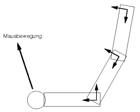
Figure 2
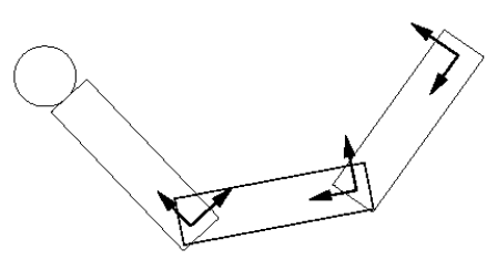
Figure 3
- You can learn more about joints in the Skeleton Animation section of the Basics 20.5 chapter
To "drag" an object, you must first activate the part that you want to change. In the case of a robot, for example, this can be the arm. If you now start the "drag" action with the mouse, MaxonCINEMA 4D determines which of the activated objects is the closest to the mouse click. This object can now be "dragged". All hierarchically superordinate objects follow it within the specified framework.
The "figure" object is particularly suitable for trying out the "drag" action. This object can be found in the "Objects" menu under the special objects. It is already structured hierarchically, so you can try “dragging” right away.
8. Turn
 With this function you can rotate the active object around its axes, around the screen or around the world axes.
Use the rotation grid to achieve greater accuracy. You can use it to rotate an object in 10° increments, for example.
Note
You can cancel the turning process with the
<Esc>key.
MaxonCINEMA 4D differentiates between the three coordinate systems world, object and screen. As long as the object is parallel to the axes of the world coordinate system — which is the case after object creation — you won't see any difference between the world and object systems. Only when the object is at an angle in space does the difference become significant.
If the active object is rotated in world or screen coordinates, then the selected world or screen axis is not used for the rotation, but an axis parallel to it and passing through the object origin. Otherwise the active object would not only be rotated, but at the same time the origin of the object coordinate system would rotate around the selected axis.
- The difference between the three systems is detailed in Chapter 6 of the Basics.
You can only rotate around one axis at a time. You control the rotation by moving the mouse left and right. It doesn't matter which of the two mouse buttons you hold down. You can use the "X", "Y" and "Z" symbols to tell the program about which axis you want to rotate.
Attention: The rotation of the camera view works according to different rules (Reference 1.1). Regardless of which system you use for rotation, the spatial position of the active object is always given in world coordinates in the "Information" window on the "Position" page.
9. Move
 With this function you can position the active object anywhere on the desktop.
When moving, MaxonCINEMA 4D distinguishes between the fixed world coordinate system, the object coordinate system and the screen coordinate system. You can use the "axis system" icon to specify in which of the three systems you want to move.
Note
Use the shift grid to achieve higher positioning accuracy. For example, you can only place objects every 10 cm.
The difference in the shift in different axis systems becomes particularly clear if you only activate the "X" symbol. Suppose you are moving a box that is crooked in the world coordinate system. If you now move in world coordinates, the cuboid moves on a parallel to the X-axis of the world coordinate system (Figure 4). On the other hand, if you choose the object coordinate system of the cuboid, the cuboid moves further along its object X-axis (Figure 5). When you select the screen coordinate system you will get a movement to the right of the screen (Figure 6).
The "X", "Y" and "Z" symbols allow you to lock specific axes. This is useful, for example, when you have constructed an object that stands on the ground plane. If you now move it in one of the perspective views, it unintentionally changes its Y value and, in the worst case, is below the ground. On the other hand, if you lock the Y icon, the object remains stationary on the ground plane and only moves in the other directions.
A right-left movement of the mouse while holding down the left mouse button moves the object in the direction of the X-axis of the screen coordinate system. An up-down movement moves the object in the direction of the Y-axis. If you press the right mouse button and carry out a right-left movement with the mouse, the object is moved forwards or backwards.
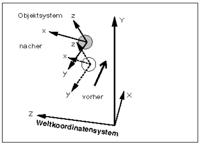
Figure 4
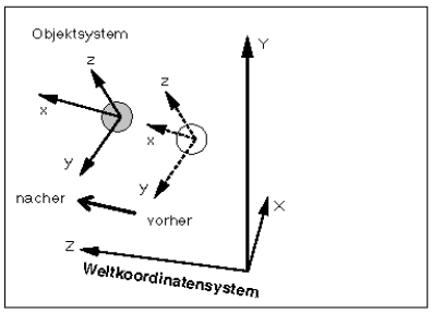
Figure 5
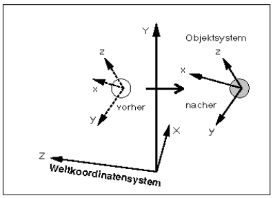
Figure 6
Mouse inputs have a slightly different meaning when editing textures. A right-left movement of the mouse shifts the texture in the direction of its X-axis and correspondingly the up-down movement of the mouse shifts the texture in the direction of its Y-axis.
As an alternative to moving with the mouse, you can also enter the displacement data manually by directly entering the values for the position in the "Information" window on the "Location" page. All values of the "Information" window are given in world coordinates.
10. Scale
 With this function you can reduce or enlarge the active object as you wish.
The scaling grid is ineffective if at least one of the three axes is closed in the screen or world system.
Note
Use the scaling grid to achieve greater accuracy. For example, you can only scale the active object so that it changes its size by a multiple of 10 cm.
When scaling, MaxonCINEMA 4D distinguishes between the fixed world coordinate system, the object coordinate system and the screen coordinate system. You can scale the active object in all three systems.
The difference between the systems becomes particularly clear if you only activate the "X" symbol. Suppose you are scaling a box that is skewed in the world coordinate system. If you now select the world coordinate system for scaling, the cuboid grows parallel to the x-axis of the world coordinate system and is thus distorted (Figure 7). On the other hand, if you select the object coordinate system of the cuboid (Figure 8), the cuboid expands along its own X-axis.
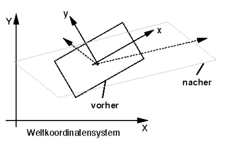
Figure 7
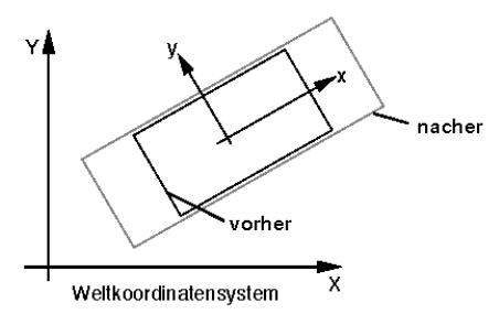
Figure 8
As just mentioned, an object can be distorted when it is scaled. This occurs whenever it is scaled in the world or screen coordinate system with one or two axes locked. In such a case, the axes of the object remain unaffected by the scaling. This is necessary so that they still form a rectangular system, which otherwise would no longer be the case. This is also the reason why the scaling grid loses its function in such a case, since it is related to the length of the axes. But since the axes don't change, the scaling grid doesn't work (it wouldn't make sense either).
The distinction between the three coordinate systems is made with the "axis system" symbol. You can lock certain axes to have the object zoom in only certain directions.
It is scaled by moving the mouse right-left. It doesn't matter which of the two mouse buttons you hold down.
Mouse inputs have a slightly different meaning when editing textures. A right-left movement of the mouse scales the texture in the direction of its X-axis and the up-down movement of the mouse scales the texture in the direction of its Y-axis.
You can also enter the data for the scaling manually by entering the values for the axis lengths directly in the "Information" window on the "Position" page.
11. X, Y, Z


The three symbols allow you to lock moving, scaling or rotating in certain axis directions.
When rotating points, objects, object axes, and texture axes, you can specify only one axis of rotation at a time. Only the camera can rotate around all three axes at the same time.
Note
MaxonCINEMA 4D remembers the status of these three symbols for each action and each type of editing. Did you have e.g. only "X" is activated and "Z" is also activated for axis scaling, then these states are noted and set again when switching over.
12. Axis system

Here you define the coordinate system in which you want to carry out an action. The three systems screen, object and world are available to you ([Basics 6]04-Basics.md#6-coordinate-systems)).
The world system is primarily used to position objects in a scene. The object system, on the other hand, is very useful for scaling individual objects, while the screen system simplifies working with the editor camera. Which system you use depends entirely on your individual case. Feel free to try out the different systems with their different effects to get a feel for it.
If you have activated all axes, you will usually not notice any difference between the individual systems. Only when certain axes are locked do the differences become apparent. In MaxonCINEMA 4D, the coordinate system of the screen is referred to as the "screen coordinate system". Its X-axis always runs from the center of a document view to the right, the Y-axis from the center up and the Z-axis down.
13. Presentation
 Here you can determine the appearance of the objects on the screen. In addition, you can activate a labeling function for objects and points.
MaxonCINEMA 4D gives you the option of accelerating the image build-up by using the 'active objects' and 'inactive objects' fields to make the following settings globally for all objects in the scene:

Figure 9
- If you set "Full", the objects are displayed with all their lines (Figure 10). The speed of the image build-up is normal.
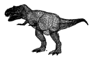
Figure 10
Note
You can save the settings made here with the "Save display as..." function of the "Project" menu. It is also possible to save default settings for the program start.
-
With the “As Box” setting, the objects are represented by enclosing boxes. This speeds up the image build-up enormously. Instead of many hundreds of lines of an object, only 12 lines are drawn (Figure 11). This type of display is particularly suitable for animation.
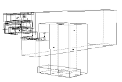
Figure 11
-
In order not to have to do without the exact display of an object as with the full display, you can select one of the levels "Slightly reduced" (Figure 12), "Medium reduced" (Figure 13) or "Highly reduced" (Figure 14). . You only draw 50% (light), 25% (medium) or 10% (strong) of all lines of an object, which is completely sufficient for irregular objects such as a dinosaur. You can still see the outlines of an object very well. In extreme cases, this speeds up the image build-up by a factor of ten. So that objects with very few lines are not affected too much by the reduction - a cube with 12 edges would only consist of a single line with a strong reduction - the reduction stages only take effect from 30 lines.
-
If you set "Invisible", then the objects are not drawn, but are still there.
Note
The "Invisible" setting is very useful for temporarily hiding objects and having fewer lines on the screen.
-
For each individual object, you can individually set in the "Information" window on the "Object" page in which of the just mentioned ways it should be displayed. If you want each item's settings to be honored, set it to As Set.
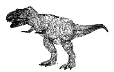
Figure 12: Slightly reduced
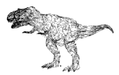
Figure 13: Medium reduced
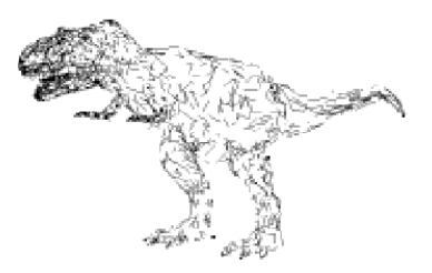
Figure 14: Greatly reduced
The origin of the objects is always drawn — regardless of the selected display type.
Because unaccelerated Amiga models are too slow to display several thousand lines in real time on the screen, a maximum number of points and objects for interactive input can be specified. If there are more elements, they will not be drawn.
-
When moving points, at most as many "points" are drawn as specified here.
-
Normally, when moving the active object, all sub-objects are also displayed with their enclosing quads. Under "Objects" you can specify how many cuboids your computer can display in real time. If MaxonCINEMA 4D determines that several sub-objects have to be left out because of the display speed, then a sophisticated procedure comes into play that preferentially selects those objects that are in a higher hierarchical position. A random number generator ensures that if possible, enveloping cuboids are drawn from all (sub)object groups, so that the outline of the object is visible.
-
Such enveloping cuboids are also drawn when changing the "View". However, since this has to happen for the whole scene, a higher value can make sense here. On the other hand, moving the scene should be quick. It is best to try out which setting suits you.
There are two annotation functions in MaxonCINEMA 4D. For one, you can 'Label objects'. If this option is activated, the name of each object is also shown on the desktop. On the other hand, there is the option of “Labeling points”. The point numbers are displayed for each point of an object — but only if you are currently editing points.
With "Show animation path" you can specify that the animation path is drawn for the active object. This option is only effective in the professional version of MaxonCINEMA 4D.
With the "Background image" function, you can display an IFF image in the background. This is especially helpful if you want to copy a scanned template (e.g. contours of letters or contour lines of a map). To do this, enter the name of the IFF file in the text field.
The image should be in two colors. If there are more colors, then MaxonCINEMA 4D only uses the first bitplane of the image. The image is not changed in size. If the image is too large for the document window, the edges will be cropped. If it is too small, margins will remain.
14. magnifying glass
 When you click on this icon, a drop-down menu with several options appears.
14.1 Magnifying glass
With the magnifying glass, you can enlarge an area of the desktop by enclosing this area with the mouse.
Immediately after selecting this function, the mouse pointer changes from an arrow to a crosshair. Now frame the desired area within the active document window. The framing works the same way as on the workbench - only it doesn't matter whether you use the left or the right mouse button for framing. You can cancel the framing with the other mouse button.
14.2 Magnify
This function enlarges the image elements by 25%. If you are in the AT view, the mouse pointer changes to a question mark. Then click on the panel that you want to enlarge.
14.3 Zoom out
With this function you reduce the image elements by 25%. When you are in 4T view, the mouse cursor changes to a question mark. Then click on the panel that you want to shrink.
14.4 Active Object
Sets the visible section of the workspace so that the active object fills the format and is centered.
In the perspective views, the camera is shifted in parallel. Your line of sight does not change.
When you are in 4T view, the mouse cursor changes to a question mark. Then click on the board you want the function to affect.
14.5 Entire scene
If you need an overview of the whole scene, you can use this function. It adjusts the visible section of the desktop so that the entire scene fills the format and is centered. The "Perspective" camera is only added to the scene when it is active.
In the perspective views, the camera is shifted in parallel. Your line of sight does not change.
When you are in 4T view, the mouse cursor changes to a question mark. Then click on the board you want the function to affect.
14.6 original size
This function sets the magnification factor to 1.0 or, in the perspective views, the camera focal length to 50mm. You will also find these settings when you start the program.
When you are in the 4T view, the mouse cursor changes to a question mark. Then click on the board you want the function to affect.
15. Redraw
 You can use this function to completely rebuild the scene.
16. Rendering
 Here you will find all the functions that you can use to calculate an image. The functions are ordered according to increasing computational effort and image quality.
Note
The scene of the active document is always calculated. Only bodies appear in the calculated image. Polygons, camera and light sources are not displayed, but only evaluated for rendering.
If you click on the "Rendering" icon, a drop-down menu appears, from which you can select the desired rendering method.
When using the left mouse button, the rendering is started immediately. Using the right mouse button a window will appear where you can specify many calculation options and the name under which the finished image should be saved.
In Figure 15 you can see how the different algorithms behave over time.
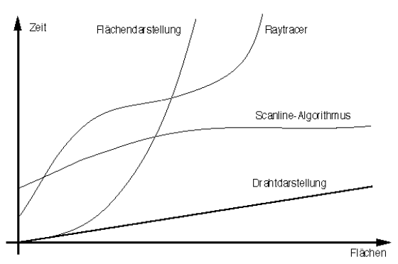
Figure 15
Wire diagram requires the least amount of computing time, essentially only time is needed for displaying the lines on the screen. The calculation time is therefore also linearly dependent on the number of surfaces. Owners of a fast graphics card benefit from the shortest build-up times for the image.
The temporal behavior of the area display is essentially determined by the sorting algorithm. Despite optimization, the time for sorting increases exponentially with the number of faces. This type of representation is therefore less suitable for scenes with several hundred thousand areas or more.
In contrast, the calculation time for the Scarline algorithm is largely constant. Its speed essentially depends only on the screen resolution used. The more pixels there are, the more calculations are required to illuminate an object. If you construct the objects more finely, the number of faces increases, but the size of the faces decreases. The product of the size and number of surfaces therefore remains practically constant, as does the computing time. This predestines the scanline algorithm for animation. The image quality is also convincing.
The ray tracing algorithm is not quite as simple. The more areas that have to be calculated, the more computing time the algorithm usually needs. However, MaxonCINEMA 4D has integrated a scanline algorithm into the raytracer (adaptive raytracer), which is used in all areas of the image where no raytracing (no transparency, no shadow, etc.) is required. This reduces the exponential increase depending on the scene and speeds up the image calculation significantly.
All calculation types have the two windows "Output" and "History" in common. The "Output" window is opened by clicking on the "Output" field in the settings. The "History" window appears on the editor screen during image calculation.
"Output" window
The "Output" window is divided into two areas: the screen and the 24-bit output.
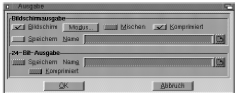
Figure 15b
"Screen Output"
For screen output, you set whether the image should be output on the "screen" at all. This is a must for the wire and surface display, but the screen output can be turned off for the scanline or ray tracing calculation. The 24-bit output must then be activated for this, because image calculation without output on the screen or hard disk makes no sense.
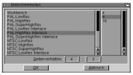
Figure 16
Set the desired screen mode under "Mode" (Basics 18). The entry "Cinema screen" always appears first in the selection list. If you select it, the image calculation takes place on the MaxonCINEMA 4D editor screen. Basically, this setting is more convenient, since no new screen has to be opened. However, there are also disadvantages. This is how the editor occupies the first 8 colors of the screen. Associated with this is a lower quality of the output image. It is optimal if the image is only used as a preview and is also saved as a 24-bit file on the hard drive. If the editor is operated in "HAM-8" mode, the output images achieve excellent quality.
For the calculation of animations, you should always redirect the image output to a separate screen. Because the output in a window on the editor screen means more effort for the Amiga operating system, so that the image calculation runs a little slower. However, since such times easily add up with an animation, you should use your own screen.
In addition, you can set the aspect ratio (Basics 18) under "Mode".
If you select "Save", the image will be saved under the path name entered in the "Name" text field. With "Compressed" you specify whether the IFF image to be saved should be compressed.
You may have noticed that, despite the Amiga's 4096 colors, color gradations are sometimes missing in color transitions. This then gives unsightly layers of paint. If you activate "Blend", a color transition is resolved by blending two adjacent colors. However, this is not true mixing (like mixing two paint pots) but mixing like newspapers are done. The different shades of gray are caused by different numbers of small black and white dots. Blending removes the layers of paint, but the image becomes grainier.
With many graphics cards, you can still see stripes or patterns in color gradients despite the 24-bit setting. Such graphics cards do not reproduce color gradients true to the original. CINEMA 4D dithers even with 16 million colors to reduce noise in smooth color gradients — unless you deactivate the Mixing option. However, the mixing only applies to the screen output and not to the hard disk output.
"24-bit output"
Each image is calculated internally with 16 million colors (this corresponds to 24 bits). A normal Amiga cannot display so many colors, only store them. To do this, enter the path name in the "Save" field under which the image with all 16 million colors is to be saved.
With "Compressed" you determine whether the 24-bit image to be saved should be compressed. Even if you don't have a graphics card, it is an advantage to first save the calculated images with 16 million colors so that they can then be converted to the Amiga color resolution using a suitable program. The image quality achieved is higher than when the image is output directly on the screen.
You must specify the aspect ratio for special output devices (e.g. slide recorders). MaxonCINEMA 4D always uses the ratio specified under "Mode", even if there is no image output at all.
"History" window
When you start the image calculation, the "History" window appears, which shows you how far the image calculation has progressed. It is usually obscured by the output screen. A mouse click on the output screen brings the "History" window to the front. Conversely, you can bring the output screen back to the foreground by clicking on the "Image" field. You can also use the keyboard shortcut 'b' (for 'image') to switch between the two screens.
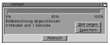
Figure 17
To cancel the image calculation, you can either click on "Cancel" or press the <Esc> key. If the image calculation is still in progress, a confirmation prompt will first appear if you cancel with <Esc>.
With "Save" you can save the output screen as an IFF image at any time. You will be asked for the file name under which the image should be saved. If you forgot to activate the "Save" option in the "Output" window, you can still save the calculated image.
16.1 SW Wire Diagram
This type of representation is practically no different from wire representation. The only difference is that the scene is only drawn in black and white.
The SW wireframe is ideal for checking animation processes. You can play back animations that you have calculated with SW wireframe directly in the editor using the "Preview" function from the "Keyframe" menu (Reference V.6.).
16.2 Wireframe
Here all the lines of the objects are drawn, similar to the 3D view (Figure 18). The output is on a separate screen. If the calculation is not black and white, MaxonCINEMA 4D selects from the existing colors those that come closest to the material colors of the objects.
Note
In the case of an image output with few colors, there can be very large differences between the actual and drawn colors.
Wireframe is best suited for a quick overview of the scene, especially for animations, as the calculation is extremely fast.
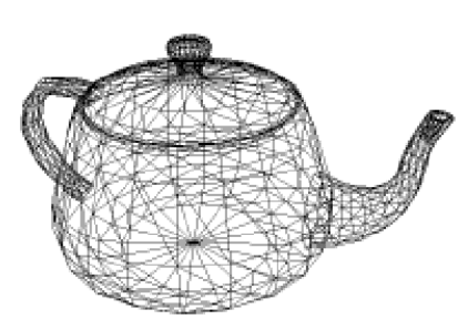
Figure 18
The ground is shown only as a horizon line. The sky is only drawn if there are more than two colors by setting the screen background to the color that is closest to it. Unlike in the 3D view, spheres are represented by meshes.
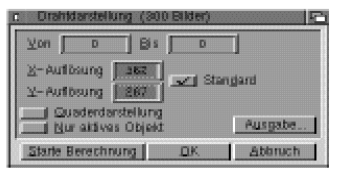
Figure 19
"From ... to"
(only effective with MaxonCINEMA 4D Professional)
If you only want to calculate part of the animation, you can enter the frame numbers that are to be calculated here. For example, you can use it to resume an interrupted image calculation. The first image has the number 0 in MaxonCINEMA 4D.
Note that with an animation you always have to specify a path name under which the images are saved. A period and a four-digit image number are appended to each name of a calculated image (e.g. "Image.0021").
Note
If you do not want an animation to be calculated, you must enter the value 0 in the "from" and "to" fields.
"X Resolution", "Y Resolution"
The X resolution and the Y resolution of the image can be freely adjusted. If the specified resolution exceeds the resolution that can be displayed on the screen, only a section of the image will be displayed. You can view the other areas of the image by moving the mouse to the edges of the screen. This moves the visible section.
"Default"
Activate this field so that the output takes place in a format-filling resolution. Otherwise you can set the resolution manually.
"Cuboid display"
You can use this option to further speed up the output. Instead of the many lines of an object, only the enveloping cuboid is drawn, which takes into account the orientation and extent of the object. This function has nothing to do with the "View" function from the main bar, as this only relates to the editor view.
"Only active object"
If you activate this option, only the active object is drawn. All other objects including ground and sky are not shown.
"Output"
If you click on this field, the "Output" window will appear, in which you can specify the type of image output (Basic 18).
"Start calculation"
Starts the calculation of the image taking into account the set values.
16.3 SW surface representation
This type of representation is practically no different from the surface representation. The only difference is that the scene is only drawn in black and white (Figure 20).
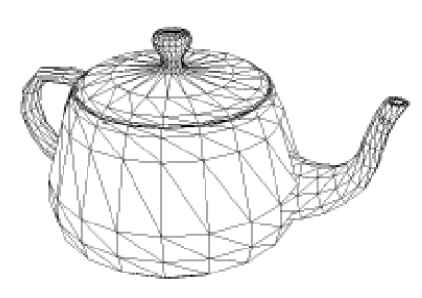
Figure 20
The SW surface display is ideal for checking animation sequences. You can play animations that you have calculated with the SW surface display directly in the editor with the "Preview" function from the "Keyframe" menu (Reference V.6).
16.4 Area representation
The plane view is more realistic than the wireframe because it only displays the visible planes and therefore does not show hidden lines (Figure 21). In addition, the visible areas are shaded in a display with more than two colors. However, only one color is used per surface, which results in a somewhat multifaceted image and no highlights are visible.
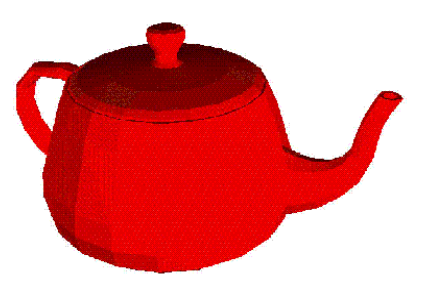
Figure 21
To suppress the hidden lines, MaxonCINEMA 4D sorts all faces of the scene from back (far from the camera) to front (close to the camera). The program then starts outputting in the order just calculated. The furthest face is drawn first, then the second furthest, etc., until finally the foremost face is reached. Areas that are further in front automatically cover the areas that are already drawn behind them.
There are problems with the calculation of the hidden lines. Please imagine two surfaces that penetrate each other. No matter which area MaxonCINEMA 4D draws first, the result does not correspond to the desired image. The surface representation cannot solve such problems. The scanline algorithm is used for this.
Sorting the areas takes a certain amount of time. Therefore, the surface representation is slower than the wire representation.
This type of calculation is particularly suitable for a rough overview of the spatial arrangement of the objects in the scene. Due to the algorithm, however, no reflections, transparencies and shadows can be calculated. Textures are also not displayed.
MaxonCINEMA 4D has an automatic light control. If you haven't defined a light source yet, MaxonCINEMA 4D calculates the scene with a default light source that is in the same place as the "Perspective" camera. This allows you to immediately view and assess objects in good lighting during the design phase. However, as soon as you create one or more normal light sources, the automatic light control is inactive unless you have deactivated it anyway in the editor settings.
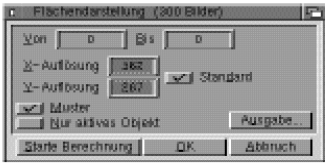
Figure 22
"From ... to"
(only effective with MaxonCINEMA 4D Professional)
If you only want to calculate part of the animation, you can enter the frame numbers that are to be calculated here. For example, you can use it to resume an interrupted image calculation. The first image has the number 0 in MaxonCINEMA 4D.
Note
If you do not want an animation to be calculated, you must enter the value 0 in the "from" and "to" fields.
Note that with an animation you always have to specify a path name under which the images are saved. A period and a four-digit image number are appended to each name of a calculated image (e.g. "Image.0021").
"X Resolution", "Y Resolution"
The X resolution and the Y resolution of the image can be freely adjusted. If the specified resolution exceeds the resolution that can be displayed on the screen, only a section of the image will be displayed. You can view the other areas of the image by moving the mouse to the edges of the screen. This moves the visible section.
"Default"
Activate this field so that the output takes place in a format-filling resolution. Otherwise you can set the resolution manually.
"Template"
If you activate this option, MaxonCINEMA 4D uses patterns to fill the areas in the color calculation. With the added mixed colors, the picture looks much better. The only thing you shouldn't do is to use patterns for animation, as they lead to a lot of noise in the picture.
"Only active object"
If you activate this option, only the active object is drawn. All other objects including ground and sky are not shown.
"Output"
If you click on this field, the "Output" window will appear, in which you can specify the type of image output (Basic 18).
Note
If you only see white objects in the surface display, you probably forgot to assign materials to the objects beforehand. Every new object in MaxonCINEMA 4D is assigned the white standard material when it is created.
"Start calculation"
Starts the calculation of the image taking into account the set values.
16.5 Scanline
You can achieve an enormous increase in quality compared to the area display with the Scansline algorithm. It doesn't sort entire surfaces like the surface display, but all points of a surface, so that penetrations and intersections are solved correctly (Figure 23).
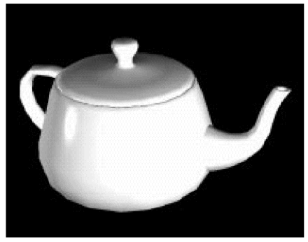
Figure 23
In addition, the scanline algorithm calculates the brightness for each individual point on a surface. Therefore, it can also display realistic transitions from light to dark, highlights and even textures.
Note
Although the scanline algorithm does not perform ray tracing, it can still display ground and sky reflections and ambient fog.
Another advantage compared to the surface display is the possibility of smoothing objects so that they no longer appear faceted but round.
For the calculation of the image, a high computational effort must be expended. So that the calculation does not take so long, a buffer is created for the depth values of the individual points in an image line. The image is calculated from top to bottom, line by line — sort of scanned and output, hence the name "scanline". After a row is calculated, it is displayed immediately.
Note
Like the surface display, the scanline algorithm has automatic lighting (Reference V.1.7.1).
MaxonCINEMA 4D uses a highly optimized scanline algorithm to achieve maximum speed. You should primarily use the scanline algorithm if you want to control the position of textures on objects and if you can do without shadows and transparency in your scene.
The scanline algorithm can display colors, highlights, all texture types and reflections of the ground and sky.
Despite certain limitations, the scanline algorithm is ideal for generating photorealistic images and is ideal for animations in particular, since the calculation time is extremely important there.
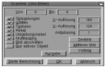
Figure 24
"From ... to"
(only effective with MaxonCINEMA 4D Professional)
If you only want to calculate part of the animation, you can enter the frame numbers that are to be calculated here. For example, you can use it to resume an interrupted image calculation. The first image has the number 0 in MaxonCINEMA 4D.
Note that when animating, you must always specify a path name under which the images will be saved. A period and a four-digit image number are appended to each name of a calculated image (e.g. "Image.0021").
Note
If you do not want an animation to be calculated, you must enter the value 0 in the "from" and "to" fields.
"Reflections"
With this option you can have the scanline algorithm calculate reflections of the ground and sky on the surfaces of specular objects. This function requires hardly any computing time and is therefore a good alternative to ray tracing for time-critical projects.
Reflections from other objects on the surface of an object are not displayed. They can only be calculated with the MaxonCINEMA 4D raytracer. Nevertheless, the simple reflection of the ground and sky is often enough.
"Smooth"
If you activate this option, objects that have the "Smooth" option (Basics 17) set are displayed smoothed ("Phong Shading").
"Textures"
Here you can set whether the scanline algorithm should display the textures used in the scene. If textures are not used, the image is calculated faster.
"Relief"
Here you can set whether relief textures are taken into account in the image calculation. Objects with materials that do not contain a bump texture are unaffected.
"Ambient Fog"
You can specify here whether the surrounding fog — if any — should be calculated.
Note
Fog objects can only be calculated correctly with the Rayftracer. In the Seanline algorithm, they appear opaque.
"Multitasking"
If many programs are running at the same time in the Amiga's multitasking mode, the speed of the individual programs is severely slowed down. In order for MaxonCINEMA 4D to be able to develop its full image calculation speed - even if many other programs in the computer's main memory are working at the same time - you can switch off multitasking during image calculation by deactivating the "Multitasking" option.
While multitasking is turned off, you cannot move the mouse, nor do keystrokes have any effect. However, so that you can cancel the image calculation anyway, multitasking is briefly switched on again after each calculated line of the image. During this time you can stop the image calculation. The abort is even quicker if you press the <Esc> key.
Note
You can make the calculated image visible at any time by pressing the key combination
<left Amiga>+M. After a while, MaxonCiNEMA 4D then automatically switches the display back to black.
"Turn off picture"
You can achieve a small increase in speed when calculating the image if you activate the "Turn off image" option. The screen is then set to black for the duration of the calculation. Because the computer no longer needs any computing time to display the image, the image calculation is slightly faster. However, this does not apply to screen modes of graphics cards. The option has no effect here.
"Only active object"
If you activate this option, only the active object is drawn. All other objects including ground and sky are not shown.
"X Resolution'', "Y Resolution"
The X resolution and the Y resolution of the image can be freely adjusted. You can use common resolutions of 320*256 pixels as well as 36000*24000 pixels (slide recorder).
If the specified resolution exceeds the resolution that can be displayed on the screen, only a section of the image will be displayed. You can view the other areas of the image by moving the mouse to the edges of the screen. This moves the visible section.
You can also set smaller resolutions such as 80*64 pixels, although the screen mode set in "Output" has a resolution of 320*256 pixels. The calculated image accordingly takes up less space on the screen and is displayed in the upper left corner.
"Antialiasing"
Since an image is always made up of a number of pixels, it has a coarse-grained structure that is all the more noticeable the lower the resolution. This grain can be seen particularly at the edges of surfaces, where nothing but small steps (the individual pixels) are visible instead of a straight edge. This phenomenon is called aliasing.
To eliminate it, there is the "Antialiasing" setting in MaxonCINEMA 4D. If you enter a value greater than 1, the image will be calculated with a higher resolution than that actually specified. This allows MaxonCINEMA 4D to average several calculated pixels for one screen pixel. This automatically inserts pixels at edges, which soften the transition between the steps of the stairs. The picture looks much better overall, details are more recognizable and annoying moiré patterns are reduced or even eliminated.
Note
The image calculation time is proportional to the pixel resolution. Twice as many pixels require twice as much calculation time. However, remember that double X and double 'Y resolution add up to four times the resolution.
The calculation time increases when antialiasing is switched on, because instead of one pixel, several pixels are now calculated and averaged. With an antialiasing level of n, n² pixels are calculated. However, the calculation time does not increase by a factor of n², since MaxonCINEMA 4D uses a highly optimized scanline algorithm. As a rule, the computing time only triples at a level of 2.
"Test image", "Middle image", "Full screen"
For a check, it is advisable to have the scene rendered in a low resolution (e.g. the size of a postage stamp).
You can use the "Test Image", "Medium Image" and "Full Image" functions so that you don't have to worry about the correct resolutions and settings every time. When you select these fields, MaxonCINEMA 4D automatically sets the correct resolutions for a small, medium-sized, or full-screen image. At the same time, the appropriate settings are made. For example, for the full image, all options are enabled for high image quality, while for the test image, most options are disabled so that the calculation is fast.
"Output"
If you click on this field, the "Output" window will appear, in which you can specify the type of image output (Basic 18).
"Start calculation"
Starts the calculation of the image taking into account the set values.
16.6 Ray Tracing
This image calculation method gives you the best image quality available (Figure 25). All properties such as shadows, transparency, refraction, textures, relief, smoothing and fog are calculated and displayed.
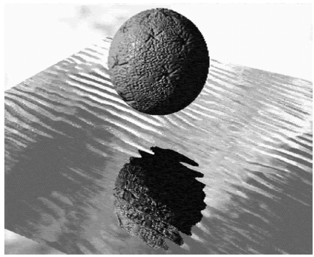
Figure 25
Note
Like the area display and scanline algorithm, the rayfracer has an automatic light control (reference v.1.7.1).
The MaxonCINEMA 4D raytracer is an adaptive raytracer, i.e. it automatically determines the points in an image where raytracing is necessary at all. An integrated scanline algorithm is used at all other points. If there are only a few objects with transparency or reflections in an image, then the image calculation is only slightly slower than in the scanline algorithm.
Because the ray tracer is very complex, it was designed as an independent program. This means that you can also start the raytracer without an editor, which saves a lot of memory. It is also possible to control the raytracer using script files (Reference V1.3.).
The ray tracing algorithm is suitable for all applications in which you need special effects such as fog or shadows. However, the calculation is very complex and can therefore take a long time.
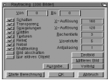
Figure 26
"Shadow"
Here you can set whether the image calculation should take place with shadow calculation. Shadow gives the scene greater plasticity.
Since additional rays have to be calculated for the shadow calculation, the image calculation becomes slower.
Note
Of course, the shadow calculation only takes place if you also use light sources for which you have previously activated the "Shadow" option.
"Transparency"
If you use materials that are transparent or have a transparency texture - possibly with refraction - then this transparency will only be displayed if you have also activated the "Transparency" option. Since the raytracer also has to calculate transparent rays, the calculation time for the image increases. Objects that are not completely closed, such as a hemisphere or a single triangle, can lead to anomalies in the image. This comes from the way the ray tracer calculates transparency and refraction. Once a ray encounters a surface with transparency and refraction, the ray will be attenuated and deflected as it passes through the surface. The beam is now in the object and continues to run until it hits another surface of the object — this time on the exit side. There it is deflected again, just as one would expect from a refracting object, for example a glass ball (Figure 27).
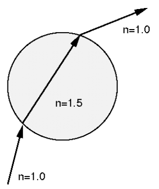
Figure 27
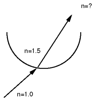
Figure 28
For example, if you use an open hemisphere, the ray will enter the hemisphere, but it may never hit a second surface (Figure 28). The ray tracer then assumes that the ray is still inside the hemisphere even though it is long outside. So don't worry about unexpected refraction effects when using open objects, and resize the objects to be closed. For example, you can give an open hemisphere a second wall (Figure 29).
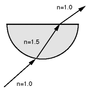
Figure 29
"Reflections"
Reflective objects are only displayed as reflective if this option is activated. It also increases the computational effort.
"Fog"
Fog objects only show a foggy appearance when the “fog” option is activated. Otherwise they are displayed opaque. Calculating fog, like transparency, requires additional computational effort and increases computation time. With this option, the calculation of the surrounding fog is activated at the same time.
For the same reason as with transparent objects, hazy objects should be closed.
"Computing depth"
When the ray tracer sends a ray into the scene, depending on the material it hits, it will be refracted and reflected. With certain arrangements of surfaces, such as two mirrors facing each other, it can happen that a ray is reflected back and forth between the two mirrors an infinite number of times. The ray tracer would never finish calculating the image. To prevent this, you can set the maximum number of reflected or refracted rays with "Calculation depth" (Figure 30).
You can also limit the calculation time for the image by using Calculation Depth. Often only the first reflections and refractions are interesting. Additional rays change the image only insignificantly, but require a disproportionately large amount of computing time.
A calculation depth of 1 means that the calculation is aborted after hitting a beam sent into the scene. Reflections and transparency are therefore not visible.
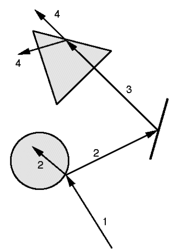
Figure 30
Note
A calculation depth of 5 is usually sufficient. You should only increase the calculation depth for very complex scenes with many reflections and transparencies.
A calculation depth of 2 means that after the first ray has hit a surface, another ray is set up for transparency and reflection.
The larger the calculation depth, the further the rays are traced into the scene and calculated.
"Voxel level"
Here you can set how many voxels the entire scene should be divided into. Common values are between 4 and 7 divisions.
The more memory you have, the higher values you can use, since memory requirements increase roughly as the cube of the subdivisions.
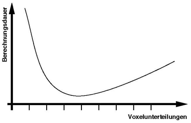
Figure 31
As a rule, the image calculation becomes faster the more voxels are present. At the same time, in addition to the memory requirement, the time required for entering the objects in the voxels also increases. In Figure 31 one can clearly see that there is an optimal voxel level for which the total time becomes minimal. This minimum reads at a voxel level of 5 to 6 for most scenes, so increasing the voxel level does not always give an improvement.
If you are not sure which value to enter, enter the value 4. Even with complex scenes, this value requires relatively little memory. You can always try a higher value afterwards.
If the ray tracer determines when entering the objects into the voxels that there is not enough memory left, it aborts the entry with a corresponding warm message. In such a case, repeat the image calculation with a smaller voxel level or make more memory available to the ray tracer.
Smooth, Textures, Emboss, Multitasking, Turn Off Image, Active Object Only, X-Resolution, Y-Resolution, Antialiasing, Output ( reference 1.16.5)
"Start calculation"
First, the active document is saved under the path specified in the editor settings so that the raytracer can access it. Then MaxonCINEMA 4D starts the ray tracer.
17. XY
 This function switches to the "XY view", which corresponds to the elevation or front view.
18.ZY
 This function switches to the "ZY view", which corresponds to the side or cross view, or the view from the side.
19. XZ
 This function switches to the "XZ view", which corresponds to the floor plan or the view from above.
20. 3D
 This function switches to the three-dimensional view. The objects are shown in perspective from the point of view of the imaginary editor camera.
21. 4T
 This view combines all of the views listed above by dividing the document window into four panels. The top left panel shows the 3D view, the bottom left shows the ZY-A view, the bottom right shows the XY view, and the top right panel shows the XZ view.
22. P
 This view switches to the three-dimensional view. The objects are drawn in perspective from the point of view of the "Perspective" camera. The editor camera is exclusively intended for the construction of the objects, while the "perspective" camera is used in the image calculation.